Asus AP1710-E1 AP1710-E1 English version manual - Page 56
in AS8 and AS4 models only
 |
View all Asus AP1710-E1 manuals
Add to My Manuals
Save this manual to your list of manuals |
Page 56 highlights
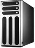
2.9.3 SCSI backplane connections (in AS8 and AS4 models only) Two SCSI backplanes come pre-installed in the AP1710-E1 AS8 model. One SCSI backplane comes pre-installed in the AS4 model. The SCSI backplane has four 68-pin SCSI connectors to support SCA SCSI hard disks. The backplane design incorporates a hot swap feature to allow easy connection or removal of SCSI hard disks. The LEDs on the backplane connect to the front panel LEDs to indicate HDD access, HDD failure, thermal failure, or fan failure. See section "1.6 LED information." Front side The front side of the SCSI backplane faces the front panel when installed. This side includes four SCSI connectors for the hot swap drive trays. Disk drive 1 Disk drive 2 Disk drive 3 Disk drive 4 HDD status LEDs HDD activity LEDs 2-32 Chapter 2: Hardware setup
-
 1
1 -
2
-
3
-
4
-
5
-
6
-
7
-
8
-
9
-
10
-
11
-
12
-
13
-
14
-
15
-
16
-
17
-
18
-
19
-
20
-
21
-
22
-
23
-
24
-
25
-
26
-
27
-
28
-
29
-
30
-
31
-
32
-
33
-
34
-
35
-
36
-
37
-
38
-
39
-
40
-
41
-
42
-
43
-
44
-
45
-
46
-
47
-
48
-
49
-
50
-
 51
51 -
 52
52 -
 53
53 -
 54
54 -
 55
55 -
 56
56 -
 57
57 -
 58
58 -
 59
59 -
 60
60 -
 61
61 -
62
-
63
-
64
-
65
-
66
-
67
-
68
-
69
-
70
-
71
-
72
-
73
-
74
-
75
-
76
-
77
-
78
-
79
-
80
-
81
-
82
-
83
-
84
-
85
-
86
-
87
-
88
-
89
-
90
-
91
-
92
-
93
-
94
-
95
-
96
-
97
-
98
-
99
-
100
-
101
-
102
-
103
-
104
-
105
-
106
-
107
-
108
-
109
-
110
-
111
-
112
-
113
-
114
-
115
-
116
-
117
-
118
-
119
-
120
-
121
-
122
-
123
-
124
-
125
-
126
-
127
-
128
-
129
-
130
-
131
-
132
-
133
-
134
-
135
-
136
-
137
-
138
-
139
-
140
-
141
-
142
-
143
-
144
-
145
-
146
-
147
-
148
-
149
-
150
-
151
-
152
-
153
-
154
-
155
-
156
-
157
-
158
 |
 |
