Asus AP1710-S5 AP1710-S5 English Manual
Asus AP1710-S5 Manual
 |
View all Asus AP1710-S5 manuals
Add to My Manuals
Save this manual to your list of manuals |
Asus AP1710-S5 manual content summary:
- Asus AP1710-S5 | AP1710-S5 English Manual - Page 1
1710-S5 Intel® Xeon Tower/5U Rackmount Server 533MHz Front Side Bus Support User Guide - Asus AP1710-S5 | AP1710-S5 English Manual - Page 2
appearing in this manual may or may not be registered trademarks or copyrights of their respective companies, and are used only for identification or explanation and to the owners' benefit, without intent to infringe. Product Name: Manual Edition: Release Date: ASUS AP1710-S5 First Edition V1 - Asus AP1710-S5 | AP1710-S5 English Manual - Page 3
Contents Notices v Safety information vi About this guide viii ASUS Contact Information x Chapter 1: Product introduction 1-1 1.1 System package contents 1-2 1.2 System specifications 1-3 1.3 Front panel features 1-4 1.4. Rear panel features 1-5 1.5 Internal features 1-6 1.6 LED - Asus AP1710-S5 | AP1710-S5 English Manual - Page 4
Contents 2.8 Cable connections 2-22 2.8.1 Motherboard connections 2-22 2.8.2 SCSI backplane connections 2-23 2.9 Removable components 2-25 2.9.1 Chassis fan 2-25 2.9.2 HDD blower 2-26 2.9.3 Floppy disk drive 2-27 2.9.4 Power supply modules 2-29 2.9.5 Power supply case 2-30 2.9.6 Roller - Asus AP1710-S5 | AP1710-S5 English Manual - Page 5
. This equipment generates, uses and can radiate radio frequency energy and, if not installed and used in accordance with manufacturer's instructions, may cause harmful interference to radio communications. However, there is no guarantee that interference will not occur in a particular installation - Asus AP1710-S5 | AP1710-S5 English Manual - Page 6
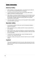
broken, do not try to fix it by yourself. Contact a qualified service technician or your dealer. Operation Safety • Any mechanical operation on this experienced engineers. • Before operating the server, carefully read all the manuals included with the server package. • Before using the server, - Asus AP1710-S5 | AP1710-S5 English Manual - Page 7
incorrectly replaced. Replace only with the same or equivalent type recommended by the manufacturer. Dispose of used batteries according to the manufacturer's instructions. CD-ROM Drive Safety Warning CLASS 1 LASER PRODUCT • Electrical hazard, do not remove chassis cover. • This equipment is to be - Asus AP1710-S5 | AP1710-S5 English Manual - Page 8
3. Appendix This appendix lists the common problems that you may encounter while using the AP1710-S5 server. It lists the possible causes of the problems and offers solutions. You may refer to this part and try to solve simple problems before calling customer support. The appendix also contains the - Asus AP1710-S5 | AP1710-S5 English Manual - Page 9
and for product and software updates. 1. ASUS PRL-DL Motherboard User Manual This manual contains detailed information about the PRL-DL motherboard. 2. ASUS Websites The ASUS websites worldwide provide updated information on ASUS hardware and software products. The ASUS websites are listed in the - Asus AP1710-S5 | AP1710-S5 English Manual - Page 10
Fax: +1-502-933-8713 General Email: [email protected] Web Site: usa.asus.com Technical Support Support Fax: +1-502-933-8713 General Support: +1-502-995-0883 Notebook Support: +1-877-918-ASUS (2787) Support Email: [email protected] ASUS COMPUTER GmbH (Germany and Austria) Address: Harkort - Asus AP1710-S5 | AP1710-S5 English Manual - Page 11
Product introduction Chapter 1 This chapter describes the general features of the AP1710-S5 server. It includes sections on front panel and rear panel specifications. ASUS AP1710-S5 user guide 1-1 - Asus AP1710-S5 | AP1710-S5 English Manual - Page 12
(2 pieces) 6. Support CDs • AP1710-S5 support CD including drivers, utilities, ASUS System Monitoring Agent (ASMA), and ASUS Server Web-Based Management (ASWM) • Trend Micro ServerProtect anti-virus software CD 7. Documentation • ASUS AP1710-S5 user guide • ASUS PRL-DL user guide • ASUS ASMS (ASMA - Asus AP1710-S5 | AP1710-S5 English Manual - Page 13
1.2 System specifications The ASUS AP1710-S5 server is a stylish server system featuring the ASUS PRL-DL motherboard. The server supports the Intel® Xeon™ processor in a 604-pin socket, and includes the latest I/O, LAN, and storage technologies through the chipsets embedded on the motherboard. - Asus AP1710-S5 | AP1710-S5 English Manual - Page 14
1.3 Front panel features The AP1710-S5 chassis displays a stylish front bezel with lock. The bezel covers the system components on the front panel and serves as security. Open the bezel to - Asus AP1710-S5 | AP1710-S5 English Manual - Page 15
port Gigabit LAN port Gigabit LAN card (optional) SCSI card (optional AC IN connector AC Power status LED 12cm fan vent Chassis lock Expansion slots ASUS AP1710-S5 user guide 1-5 - Asus AP1710-S5 | AP1710-S5 English Manual - Page 16
1.5 Internal features The AP1710-S5 chassis includes the basic components as shown in the picture below. 1 4 7 5 2 PCI slots 7. CPU sockets 8. Internal 68-pin SCSI cable 9. PCI long card support guide 10. 12 cm hot swap module blower 11. PRL-DL motherboard 12. Chassis intrusion sensor 1-6 - Asus AP1710-S5 | AP1710-S5 English Manual - Page 17
1.6 LED information The AP1710-S5 comes with five LED indicators. Refer to the picture for the LED location and the following table for the LED status a HW monitor event The Power, HDD Access and Message LEDs are visible even if the system front bezel is closed. ASUS AP1710-S5 user guide 1-7 - Asus AP1710-S5 | AP1710-S5 English Manual - Page 18
1-8 Chapter 1: Product introduction - Asus AP1710-S5 | AP1710-S5 English Manual - Page 19
Chapter 2 This chapter lists the hardware setup procedures that you have to perform when installing or removing system components. Hardware setup ASUS AP1710-S5 user guide 2-1 - Asus AP1710-S5 | AP1710-S5 English Manual - Page 20
2.1 Chassis cover Before proceeding, prepare a Phillips and a flat head screw drivers that you might need to facilitate installation. 2.1.1 Removing the cover 1. Loosen the two thumb screws that secure the side cover. 2. Slide the side cover for about half an inch toward the rear until it is - Asus AP1710-S5 | AP1710-S5 English Manual - Page 21
2.2 Motherboard information The AP1710-S5 comes with the ASUS PRL-DL motherboard that uses the extended ATX form factor measuring 12 inches x 10.5 This side towards the rear of the chassis Refer to the motherboard user guide for detailed information on the motherboard. ASUS AP1710-S5 user guide 2-3 - Asus AP1710-S5 | AP1710-S5 English Manual - Page 22
533/400MHz system bus, and execution trace cache. Together, these attributes improve system performance by allowing higher core frequencies, faster execution of integer instructions, and data transfer rate of up to 4.26GB/s. ® PRL-DL Gold Arrow PRL-DL Socket 604 Gold Arrow Prestonia 400Mhz FSB - Asus AP1710-S5 | AP1710-S5 English Manual - Page 23
2.3.1 Installing the CPU The motherboard supports either one or two CPUs. If you are installing only one CPU, you MUST install it in CPU socket 1. Follow these steps to the socket lever to secure the CPU. The lever clicks on the side tab to indicate that it is locked. ASUS AP1710-S5 user guide 2-5 - Asus AP1710-S5 | AP1710-S5 English Manual - Page 24
2.3.2 Installing the heatsink and fan The Intel® Xeon™ processors require specially designed heatsink and fan assembly to ensure optimum thermal condition and performance. Make sure that the heatsink with fan assembly is properly installed on the motherboard. A tilted or improperly installed - Asus AP1710-S5 | AP1710-S5 English Manual - Page 25
same steps if you will install another CPU in the second CPU socket. 6. Use CPUFAN2 connector for the second CPU heatsink and fan assembly cable. ASUS AP1710-S5 user guide 2-7 - Asus AP1710-S5 | AP1710-S5 English Manual - Page 26
operations in one clock cycle, thus providing twice the throughput of SDR memory. For example, a 200MHz DDR DIMM will support a 100MHz memory bus, and a 266MHz DDR DIMM will support a 133MHz memory bus. DDR Data Transfer Rate 266MHz 200MHz DDR Base Frequency 133MHz 100MHz A DDR DIMM has the same - Asus AP1710-S5 | AP1710-S5 English Manual - Page 27
SDRAM 128MB, 256MB, 512MB, 1GB, 2GB (x1) = SDRAM 128MB, 256MB, 512MB, 1GB, 2GB (x1) = Total System Memory (Max. 4GB) = The system chipset only supports PC2100/PC1600 registered ECC DIMMs. Make sure to use only the specified DIMM types for stable system operation. ASUS AP1710-S5 user guide 2-9 - Asus AP1710-S5 | AP1710-S5 English Manual - Page 28
Follow these steps to remove a DIMM. 1. Press the retaining clips outward simultaneously to unlock the DIMM. 2. Remove the DIMM from the socket. 2-10 Support the DIMM lightly with your fingers when pressing the retaining clips. The DIMM might get damaged when it flips out with extra force. Chapter - Asus AP1710-S5 | AP1710-S5 English Manual - Page 29
right side. To remove the front panel assembly: 1. Use a flat-head screwdriver to detach the hooked tabs from the left side of the front panel. 1 ASUS AP1710-S5 user guide Hooked tab 2-11 - Asus AP1710-S5 | AP1710-S5 English Manual - Page 30
2. Pull and swing the left edge of the front panel outward. 3. Unhook the hinge-like tabs from the holes on the right side of the front panel to completely detach the front panel assembly from the chassis. 3 Hinge-like tab 2 Do not use too much force when removing the front panel assembly.. 2.5.2 - Asus AP1710-S5 | AP1710-S5 English Manual - Page 31
is in place. 4 The drive is in place when the screw holes on the drive align with the holes on the side of the bay. ASUS AP1710-S5 user guide 2-13 - Asus AP1710-S5 | AP1710-S5 English Manual - Page 32
5. Secure the drive to the bay using the screwless drive bay lock that you removed earlier. a. Match the two pegs on the lock to the holes on the drive bay. b. Turn the knob 45º clockwise until it clicks on the reference point near the "locked icon." Reference point 5a 5b Locked icon 6. On the - Asus AP1710-S5 | AP1710-S5 English Manual - Page 33
left and fit the four (4) hooked tabs to the left side of the chassis until the tabs snap in place. 7a 7b Hinge-like tab ASUS AP1710-S5 user guide 2-15 - Asus AP1710-S5 | AP1710-S5 English Manual - Page 34
2.6 Hard disk drives The AP1710-S5 comes with six externally accessible drive bays. In each drive bay is a removable tray for mounting an SCA SCSI hard disk drive. 2.6.1 Installing a hard disk - Asus AP1710-S5 | AP1710-S5 English Manual - Page 35
5. Insert the hard disk drive tray into the bay until it fits. 6. Push the tray lever back in place. Make sure that the HDD tray is completely in place before you push the handle back to avoid damaging the drive and the tray. ASUS AP1710-S5 user guide 2-17 - Asus AP1710-S5 | AP1710-S5 English Manual - Page 36
2.7 Expansion cards The chassis is designed with a screwless expansion slot frame on the rear panel. This design feature allows you to install or remove an expansion card in less steps. Make sure to unplug the power cord before installing or removing expansion cards. Failure to do so may cause - Asus AP1710-S5 | AP1710-S5 English Manual - Page 37
click indicates that the card is locked in place. Lock 4 4 Refer to the card documentation for the card configuration details, and to the motherboard user guide in case you need to configure any jumpers after installing the expansion card. ASUS AP1710-S5 user guide 2-19 - Asus AP1710-S5 | AP1710-S5 English Manual - Page 38
(under the backplane board) to keep the expansion cards firmly seated on the slots. This card support has individual card guides that correspond to each expansion slot. Plastic long-card support To install a long expansion card: 1. Position the expansion card above the PCI slot that you wish - Asus AP1710-S5 | AP1710-S5 English Manual - Page 39
lock 1a 1b 2. Pull out the card from the PCI slot. 2 3. Press the end of the card lock marked "LOCK" to return it in place. ASUS AP1710-S5 user guide 2-21 - Asus AP1710-S5 | AP1710-S5 English Manual - Page 40
2.8 Cable connections 2.8.1 Motherboard connections The AP1710-S5 chassis includes the power and signal cables that you need to connect power 11. 8-pin 12V AUX power 12. SCSI controller Refer to the motheboard user guide for detailed information on the connectors. 2-22 Chapter 2: Hardware setup - Asus AP1710-S5 | AP1710-S5 English Manual - Page 41
backplane has six 68-pin SCSI connectors to support SCA SCSI hard disks. The backplane design incorporates 3 Disk drive 4 SCSI ID = 4 Disk drive 5 SCSI ID = 5 Disk drive 6 ASUS AP1710-S5 user guide 68-pin SCSI connector (connect to the SCSI connector on the motherboard) SMBus connector (connect to - Asus AP1710-S5 | AP1710-S5 English Manual - Page 42
The following picture shows the SCSI backplane installed in the system and the cables connected to it. Power cables from power supply SMBus cable from power supply SMBus cable from motherboard connector Fan cables SCSI cable Fan cable Use power plugs from both redundant power supply modules to - Asus AP1710-S5 | AP1710-S5 English Manual - Page 43
the fan from the inside of the chassis. Pin lock (tail-end) 3. Pull out the pin locks from the rear panel. 4. Remove the chassis fan. ASUS AP1710-S5 user guide 2-25 - Asus AP1710-S5 | AP1710-S5 English Manual - Page 44
2.9.2 HDD blower To remove the HDD blower: 1. Disconnect the 3-pin HDD blower cable from the FAN 1 connector on the SCSI backplane. 1 2. Press the tab at the bottom of the blower to release it from the chassis. 3. Pull out the HDD blower. HDD blower cable HDD blower 3 HDD blower 2 Blower tab 2- - Asus AP1710-S5 | AP1710-S5 English Manual - Page 45
chassis cover screws. 2 3. Pull out and detach the right side chassis cover. Set aside the cover. 3 4. Locate the floppy disk drive cable and power connectors. 4 ASUS AP1710-S5 user guide 2-27 - Asus AP1710-S5 | AP1710-S5 English Manual - Page 46
5. Detach the floppy disk drive cable. 6. Detach the floppy disk drive power cable. 7. Squeeze the floppy disk drive tray tabs while pulling the tray out of the chassis. Floppy disk drive tray 2-28 Chapter 2: Hardware setup - Asus AP1710-S5 | AP1710-S5 English Manual - Page 47
2.9.4 Power supply modules The AP1710-S5 has two power supply modules. These hot swap power modules can be removed or installed while the Housing Screw 2 1 500W Redundant Power Module 3 Lever Refer to the Appendix for the redundant power module specification. ASUS AP1710-S5 user guide 2-29 - Asus AP1710-S5 | AP1710-S5 English Manual - Page 48
2.9.5 Power supply case The redundant power modules are secured in a power supply case that connects to various power supply connectors on the SCSI backplane and the motherboard. To remove the power supply case: 1. Remove the two (2) top chassis cover screws to release chassis top panel cover. 2. - Asus AP1710-S5 | AP1710-S5 English Manual - Page 49
screws. 6. Remove the six (6) power case top screws. Make sure the power case is well supported or held when releasing the power case screws. The power case may accidentally drop and cause damage to other server system components. 7. Slowly pull-out the power case. ASUS AP1710-S5 user guide 2-31 - Asus AP1710-S5 | AP1710-S5 English Manual - Page 50
bottom of the chassis. Brake lock Remove the chassis roller wheels if you wish to mount the system to a rack. Refer to the Rackmount Kit manual for more information. 2-32 Chapter 2: Hardware setup - Asus AP1710-S5 | AP1710-S5 English Manual - Page 51
-S5 server. It lists the possible causes of the problems and offers solutions. You may refer to this part and try to solve simple problems before calling customer support. The appendix also contains the redundant power module specifications for your reference. Appendix ASUS AP1710-S5 user guide - Asus AP1710-S5 | AP1710-S5 English Manual - Page 52
on the system or the components. These problems only requires simple troubleshooting actions that you can perform by yourself. Problem Action The power LED on the server DIMMs the system supports. 2. Make sure that the DIMMs are properly installed on the sockets. A-2 Appendix: Troubleshooting - Asus AP1710-S5 | AP1710-S5 English Manual - Page 53
Problem Action The system continuously beeps after it was turned on 1. Check the memory modules and make sure you installed the DIMMs the system supports. 2. Make sure that the DIMMs are properly installed on you have installed the LAN drivers from the support CD. ASUS AP1710-S5 user guide A-3 - Asus AP1710-S5 | AP1710-S5 English Manual - Page 54
5.5 6.5 +12V 12.9 14.2 Max (V) 3.50 5.25 12.60 -13.20 5.25 Ripple/Noise 50mVp-p 50mVp-p 120mVp-p 120mVp-p 50mVp-p Max. Load (W) 81.6 87.5 300 2.4 10 A-4 Appendix: Troubleshooting
-
 1
1 -
 2
2 -
 3
3 -
 4
4 -
 5
5 -
 6
6 -
 7
7 -
8
-
9
-
10
-
11
-
12
-
13
-
14
-
15
-
16
-
17
-
18
-
19
-
20
-
21
-
22
-
23
-
24
-
25
-
26
-
27
-
28
-
29
-
30
-
31
-
32
-
33
-
34
-
35
-
36
-
37
-
38
-
39
-
40
-
41
-
42
-
43
-
44
-
45
-
46
-
47
-
48
-
49
-
50
-
51
-
52
-
53
-
54
 |
 |
Intel
®
Xeon Tower/5U Rackmount Server
533MHz Front Side Bus Support
1710-S5
User Guide