Asus AP1710-S5 AP1710-S5 English Manual - Page 48
Power supply case
 |
View all Asus AP1710-S5 manuals
Add to My Manuals
Save this manual to your list of manuals |
Page 48 highlights
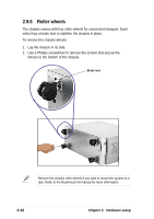
2.9.5 Power supply case The redundant power modules are secured in a power supply case that connects to various power supply connectors on the SCSI backplane and the motherboard. To remove the power supply case: 1. Remove the two (2) top chassis cover screws to release chassis top panel cover. 2. Remove all power cable connections from SCSI backplane and motherboard. 3. Remove the six (6) chassis bar screws and release chassis bar. 4. Remove the two (2) right-side chassis cover screws to release right-side cover. 2-30 Chapter 2: Hardware setup
-
 1
1 -
2
-
3
-
4
-
5
-
6
-
7
-
8
-
9
-
10
-
11
-
12
-
13
-
14
-
15
-
16
-
17
-
18
-
19
-
20
-
21
-
22
-
23
-
24
-
25
-
26
-
27
-
28
-
29
-
30
-
31
-
32
-
33
-
34
-
35
-
36
-
37
-
38
-
39
-
40
-
41
-
42
-
 43
43 -
 44
44 -
 45
45 -
 46
46 -
 47
47 -
 48
48 -
 49
49 -
 50
50 -
 51
51 -
 52
52 -
 53
53 -
54
 |
 |

Chapter 2:
Hardware setup
2-30
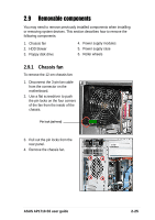
2.9.5
Power supply case
The redundant power modules are secured in a power supply case that
connects to various power supply connectors on the SCSI backplane and
the motherboard.
To remove the power supply case:
1.
Remove the two (2) top
chassis cover screws to release
chassis top panel cover.
2.
Remove all power cable
connections from SCSI
backplane and motherboard.
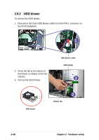
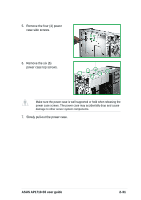
4.
Remove the two (2) right-side
chassis cover screws to release
right-side cover.
3.
Remove the six (6) chassis bar
screws and release chassis bar.