Asus AP1710-S5 AP1710-S5 English Manual - Page 40
Cable connections
 |
View all Asus AP1710-S5 manuals
Add to My Manuals
Save this manual to your list of manuals |
Page 40 highlights
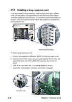
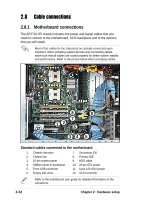
2.8 Cable connections 2.8.1 Motherboard connections The AP1710-S5 chassis includes the power and signal cables that you need to connect to the motherboard, SCSI backplane and to the devices that you will install. Most of the cables for the chassis kit are already connected upon shipment. When installing system devices and connecting cables, make sure that all cables are routed properly for better system stability and performance. Refer to the picture below when arranging cables. 11 10 8 9 7 12 12 6 34 5 Standard cables connected to the motherboard 1. Chassis intrusion 2. Chassis fan 3. 20-pin system panel 4. SMBus panel to backplane 5. Front USB connector 6. Floppy disk drive 7. Secondary IDE 8. Primary IDE 9. HDD cable 10. 24-pin ATX power 11. 8-pin 12V AUX power 12. SCSI controller Refer to the motheboard user guide for detailed information on the connectors. 2-22 Chapter 2: Hardware setup
-
 1
1 -
2
-
3
-
4
-
5
-
6
-
7
-
8
-
9
-
10
-
11
-
12
-
13
-
14
-
15
-
16
-
17
-
18
-
19
-
20
-
21
-
22
-
23
-
24
-
25
-
26
-
27
-
28
-
29
-
30
-
31
-
32
-
33
-
34
-
 35
35 -
 36
36 -
 37
37 -
 38
38 -
 39
39 -
 40
40 -
 41
41 -
 42
42 -
 43
43 -
 44
44 -
 45
45 -
46
-
47
-
48
-
49
-
50
-
51
-
52
-
53
-
54
 |
 |
