Asus AP1710-S5 AP1710-S5 English Manual - Page 29
-inch drives
 |
View all Asus AP1710-S5 manuals
Add to My Manuals
Save this manual to your list of manuals |
Page 29 highlights
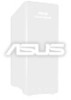
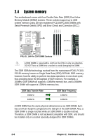
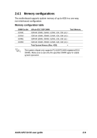
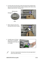
2.5 5.25-inch drives If you have previously used and powered up the system, and that it may be connected to an AC power source, make sure to unplug the power cable before installing or removing any system components. Failure to do so may cause severe damage to the motherboard and other system components! Three 5.25-inch drive bays are located on the upper front part of the chassis. A CD-ROM drive that comes 1 standard with the system package occupies the uppermost bay (labeled 2 1). The two lower bays (labeled 2 and 3) are available for additional 3 5.25-inch devices. 2.5.1 Removing the front panel assembly Before you can install a 5.25-inch drive, you should first remove the front panel assembly (front bezel and front panel cover). The front panel assembly is attached to the chassis through four hooked tabs on the left side and four hinge-like tabs on the right side. To remove the front panel assembly: 1. Use a flat-head screwdriver to detach the hooked tabs from the left side of the front panel. 1 ASUS AP1710-S5 user guide Hooked tab 2-11
-
 1
1 -
2
-
3
-
4
-
5
-
6
-
7
-
8
-
9
-
10
-
11
-
12
-
13
-
14
-
15
-
16
-
17
-
18
-
19
-
20
-
21
-
22
-
23
-
 24
24 -
 25
25 -
 26
26 -
 27
27 -
 28
28 -
 29
29 -
 30
30 -
 31
31 -
 32
32 -
 33
33 -
 34
34 -
35
-
36
-
37
-
38
-
39
-
40
-
41
-
42
-
43
-
44
-
45
-
46
-
47
-
48
-
49
-
50
-
51
-
52
-
53
-
54
 |
 |