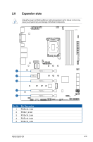
Asus ExpertCenter E500 G9 E500 G9 English User Manual - Page 42
Remove the screw on the stand screw., optional Remove the stand screw
 |
View all Asus ExpertCenter E500 G9 manuals
Add to My Manuals
Save this manual to your list of manuals |
Page 42 highlights
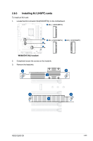
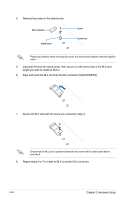
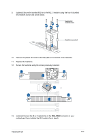
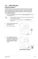
4. Remove the screw on the stand screw. M.2 connector Stand screw Screw Screw hole Please pay attention when removing the screw, the stand screw might be removed together with it. 5. (optional) Remove the stand screw, then secure it to the screw hole of the M.2 card length you wish to install an M.2 to. 6. Align and insert the M.2 card into the M.2 connector (M.2(SOCKET3)). 7. Secure the M.2 card with the screw you removed in step 4. Ensure that the M.2 card is positioned between the screw and the stand screw before securing it. 8. Repeat steps 4 to 7 to install an M.2 to another M.2 connector. 2-24 Chapter 2: Hardware Setup
-
 1
1 -
2
-
3
-
4
-
5
-
6
-
7
-
8
-
9
-
10
-
11
-
12
-
13
-
14
-
15
-
16
-
17
-
18
-
19
-
20
-
21
-
22
-
23
-
24
-
25
-
26
-
27
-
28
-
29
-
30
-
31
-
32
-
33
-
34
-
35
-
36
-
 37
37 -
 38
38 -
 39
39 -
 40
40 -
 41
41 -
 42
42 -
 43
43 -
 44
44 -
 45
45 -
 46
46 -
 47
47 -
48
-
49
-
50
-
51
-
52
-
53
-
54
-
55
-
56
-
57
-
58
-
59
-
60
-
61
-
62
-
63
-
64
-
65
-
66
-
67
-
68
-
69
-
70
-
71
-
72
-
73
-
74
-
75
-
76
-
77
-
78
-
79
-
80
-
81
-
82
-
83
-
84
-
85
-
86
-
87
-
88
-
89
-
90
-
91
-
92
-
93
-
94
-
95
-
96
-
97
-
98
-
99
-
100
-
101
-
102
-
103
-
104
-
105
-
106
-
107
-
108
-
109
-
110
-
111
-
112
-
113
-
114
-
115
-
116
-
117
-
118
-
119
-
120
-
121
-
122
-
123
-
124
-
125
-
126
-
127
-
128
-
129
-
130
-
131
-
132
-
133
-
134
-
135
-
136
-
137
-
138
-
139
-
140
-
141
-
142
-
143
-
144
-
145
-
146
-
147
-
148
-
149
-
150
-
151
-
152
-
153
-
154
-
155
-
156
-
157
-
158
-
159
-
160
-
161
-
162
-
163
-
164
-
165
-
166
-
167
-
168
-
169
-
170
-
171
-
172
-
173
-
174
-
175
-
176
-
177
-
178
-
179
-
180
-
181
-
182
-
183
-
184
-
185
-
186
 |
 |

Chapter 2: Hardware Setup
2-24
Ensure that the M.2 card is positioned between the screw and the stand screw before
securing it.
Please pay attention when removing the screw, the stand screw might be removed together
with it.
Stand screw
Screw
M.2 connector
Screw hole
4.
Remove the screw on the stand screw.
5.
(optional) Remove the stand screw, then secure it to the screw hole of the M.2 card
length you wish to install an M.2 to.
6.
Align and insert the M.2 card into the M.2 connector (M.2(SOCKET3)).
7.
Secure the M.2 card with the screw you removed in step 4.
8.
Repeat steps 4 to 7 to install an M.2 to another M.2 connector.