Asus KFN4-D16 User Guide - Page 33
System memory
 |
UPC - 610839141265
View all Asus KFN4-D16 manuals
Add to My Manuals
Save this manual to your list of manuals |
Page 33 highlights
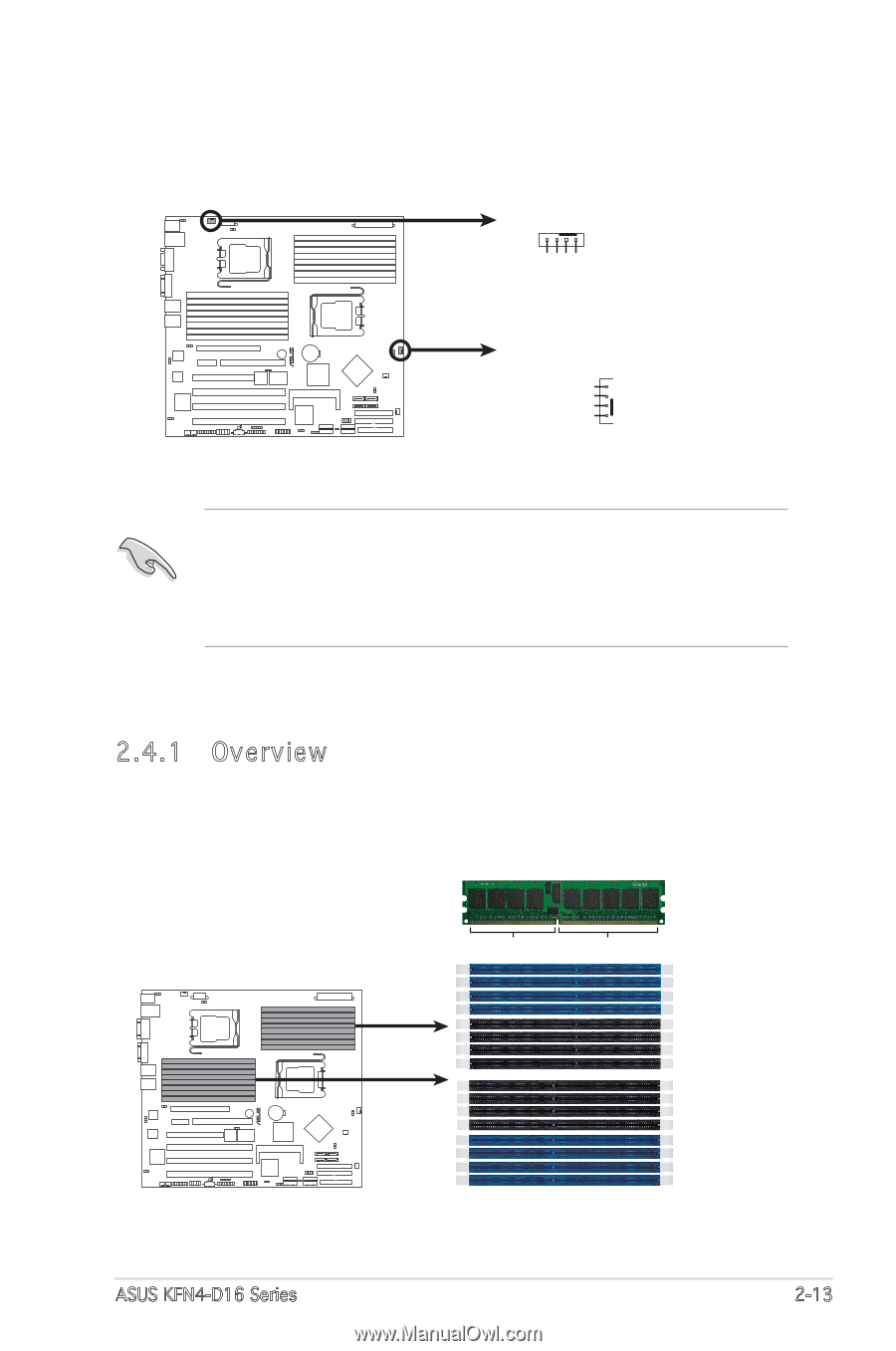
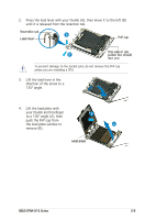
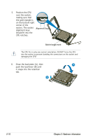
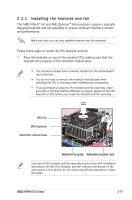
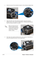
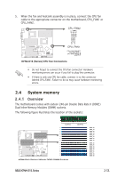
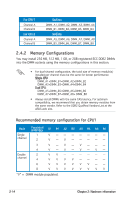
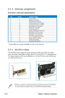
5. When the fan and heatsink assembly is in place, connect the CPU fan cable to the appropriate connector on the motherboard, CPU_FAN1 or CPU_FAN2. CPU_FAN2 GND CPU FAN PWR CPU FAN IN CPU FAN PWM KFN4-D16/SAS CPU_FAN1 CPU FAN PWM CPU FAN IN CPU FAN PWR GND KFN4-D16 (Series) CPU Fan Connectors • Do not forget to connect the CPU fan connector! Hardware monitoring errors can occur if you fail to plug this connector. • If there is only one CPU fan cable, connect it to the connector labeled CPU_FAN1. Failure to do so may cause hardware monitoring errors. 2.4 System memory 2.4.1 Overview The motherboard comes with sixteen 240-pin Double Data Rate II (DDR2) Dual Inline Memory Modules (DIMM) sockets. The following figure illustrates the location of the sockets: 112 Pins KFN4-D16/SAS KFN4-D16 (Series) 240-pin DDR2 DIMM Sockets 128 Pins DIMM_B4 DIMM_A4 DIMM_B3 DIMM_A3 DIMM_B2 DIMM_A2 DIMM_B1 DIMM_A1 DIMM_A5 DIMM_B5 DIMM_A6 DIMM_B6 DIMM_A7 DIMM_B7 DIMM_A8 DIMM_B8 ASUS KFN4-D16 Series 2-13
-
 1
1 -
2
-
3
-
4
-
5
-
6
-
7
-
8
-
9
-
10
-
11
-
12
-
13
-
14
-
15
-
16
-
17
-
18
-
19
-
20
-
21
-
22
-
23
-
24
-
25
-
26
-
27
-
 28
28 -
 29
29 -
 30
30 -
 31
31 -
 32
32 -
 33
33 -
 34
34 -
 35
35 -
 36
36 -
 37
37 -
 38
38 -
39
-
40
-
41
-
42
-
43
-
44
-
45
-
46
-
47
-
48
-
49
-
50
-
51
-
52
-
53
-
54
-
55
-
56
-
57
-
58
-
59
-
60
-
61
-
62
-
63
-
64
-
65
-
66
-
67
-
68
-
69
-
70
-
71
-
72
-
73
-
74
-
75
-
76
-
77
-
78
-
79
-
80
-
81
-
82
-
83
-
84
-
85
-
86
-
87
-
88
-
89
-
90
-
91
-
92
-
93
-
94
-
95
-
96
-
97
-
98
-
99
-
100
-
101
-
102
-
103
-
104
-
105
-
106
-
107
-
108
-
109
-
110
-
111
-
112
-
113
-
114
-
115
-
116
-
117
-
118
-
119
-
120
-
121
-
122
-
123
-
124
-
125
-
126
-
127
-
128
-
129
-
130
-
131
-
132
-
133
-
134
-
135
-
136
-
137
-
138
-
139
-
140
-
141
-
142
 |
 |