Asus P2B-N P2B-N User Manual - Page 15
ASUS P2B-N User's Manual, Riser Card Expansion Slots, Riser Card Connectors - p2b manual
 |
View all Asus P2B-N manuals
Add to My Manuals
Save this manual to your list of manuals |
Page 15 highlights
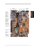
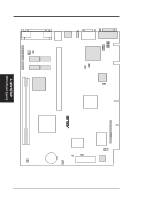
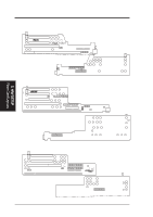
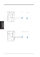
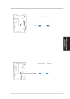
3. H/W SETUP Riser Card Contents 3. HARDWARE SETUP Riser Card Expansion Slots 1) ISA (NLX-R) p. 30 ISA (B9-N) SLOT1/1A (Yeong-Yang) 2) PCI1, PCI2 (NLX-R) p. 30 PCI1, PCI2, PCI3 (B9-N) PCI1, PCI2 (Yeong-Yang) Riser Card Connectors 1) CDIN (Yeong-Yang) p. 36 2) LAN_LED (NLX-R) p. 37 WOL_CON (NLX-R) WAKEUP (B9-N) WOL_CON (Yeong-Yang) 3) FCON (NLX-R) p. 37 HEAD_SPK (NLX-R) LED_CTRL (B9-N) HEAD_SPK (B9-N) PANEL (Yeong-Yang) 4) MIC-CON (NLR-R) p. 38 JP-2K (B9-N) MIC (Yeong-Yang) 5) POWER p. 38 ATXPWR Power 6) IDE1 (NLX-R) p. 39 IDEA, IDEB (B9-N) IDE1, IDE2 (Yeong-Yang) 7) FLOPPY (NLX-R) p. 39 FLOPPY (B9-N) FLOPPY (Yeong-Yang) 8) USB (NLX-R) p. 40 USB1 (B9-N) USB (Yeong-Yang) 9) IR, CIR (NLX-R) p. 40 IR (B9-N) IR (Yeong-Yang) 16-bit ISA Bus Expansion Slots* 16-bit ISA Bus Expansion Slots 16-bit ISA Bus Expansion Slots 32-bit PCI Bus Expansion Slots 32-bit PCI Bus Expansion Slots 32-bit PCI Bus Expansion Slots Stereo Audio In Connector LAN Activity LED Connector (2 pins) Wake-On-LAN Connector (3 pins) Wake-On-LAN Connector (3 pins) Wake-On-LAN Connector (3 pins) Front Panel Connector (16-1 pins) Speaker Connector (4-1 pins) Front Panel Connector (16-1 pins) Speaker Connector (4-1 pins) Front Panel Connector (16-1 pins) Front Panel Microphone Jack Connector (2 pins) Front Panel Microphone Jack Connector (2 pins) Front Panel Microphone Jack Connector (2 pins) NLX Power Supply Connector (20-pin block) NLX Power Supply Connector (20-pin block) NLX Power Supply Connector (20-pin block) IDE Connector (40-1 pins) IDE Connectors (40-1 pins) IDE Connectors (40-1 pins) Floppy Drive Connector (34-1 pins) Floppy Drive Connector (34-1 pins) Floppy Drive Connector (34-1 pins) USB Ports (Two 4-pin sockets) USB Ports (Two 4-pin sockets) USB Module Connector (5-1 pins) IrDA-Compliant Infrared Module (Lenses) Infrared Module Connector (10-1 pins) Infrared Module Connector (5-1 pins) * The optional onboard hardware monitor uses the address 290H-297H, so legacy ISA cards must not use this address or else conflicts will occur. ASUS P2B-N User's Manual 15
-
 1
1 -
2
-
3
-
4
-
5
-
6
-
7
-
8
-
9
-
 10
10 -
 11
11 -
 12
12 -
 13
13 -
 14
14 -
 15
15 -
 16
16 -
 17
17 -
 18
18 -
 19
19 -
 20
20 -
21
-
22
-
23
-
24
-
25
-
26
-
27
-
28
-
29
-
30
-
31
-
32
-
33
-
34
-
35
-
36
-
37
-
38
-
39
-
40
-
41
-
42
-
43
-
44
-
45
-
46
-
47
-
48
-
49
-
50
-
51
-
52
-
53
-
54
-
55
-
56
-
57
-
58
-
59
-
60
-
61
-
62
-
63
-
64
-
65
-
66
-
67
-
68
-
69
-
70
-
71
-
72
-
73
-
74
-
75
-
76
-
77
-
78
-
79
-
80
-
81
-
82
-
83
-
84
-
85
-
86
-
87
-
88
-
89
-
90
-
91
-
92
-
93
-
94
-
95
-
96
-
97
-
98
-
99
-
100
-
101
-
102
-
103
-
104
-
105
-
106
-
107
-
108
-
109
-
110
-
111
-
112
-
113
-
114
-
115
-
116
-
117
-
118
-
119
-
120
 |
 |
