Asus P2B-N P2B-N User Manual - Page 38
ASUS P2B-N User's Manual, Front Panel Microphone Connector 2-pin MIC-CON, NLX Power Supply Connector
 |
View all Asus P2B-N manuals
Add to My Manuals
Save this manual to your list of manuals |
Page 38 highlights
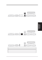
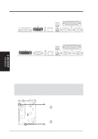
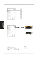
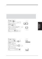
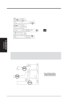
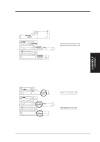
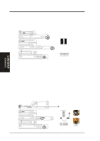
3. H/W SETUP Connectors 3. HARDWARE SETUP 4) Front Panel Microphone Connector (2-pin MIC-CON) This connector is used to connect the front panel microphone jack to the motherboard through a ribbon cable. ® NLX-R NLX-R (Front) ® B9-N B9-N (Front) The front panel's 1/8" microphone jack connects to the riser card through a ribbon cable Yeong-Yang (Front) YEONG-YANG Front Panel Microphone Jack 5) NLX Power Supply Connector (20-pin block) This connector connects to an NLX power supply. The plug from the power supply will only insert in one orientation because of the different size holes. Find the proper orientation and push down firmly making sure that the pins are aligned. IMPORTANT: Make sure that the NLX power supply can deliver at least 720mA on the 5volt standby lead (+5VSB). You may experience difficulty in powering ON your system without this specification. NLX-R (Back) +5.0 Volts +5.0 Volts -5.0 Volts Ground Ground Ground Power Supply On Ground -12.0 Volts +3.3 Volts B9-N (Back) +12.0 Volts +5V Standby Power Good Ground +5.0 Volts Ground +5.0 Volts Ground +3.3 Volts +3.3 Volts Yeong-Yang (Back) NLX Power Connector NLX Power Supply Connector 38 ASUS P2B-N User's Manual
-
 1
1 -
2
-
3
-
4
-
5
-
6
-
7
-
8
-
9
-
10
-
11
-
12
-
13
-
14
-
15
-
16
-
17
-
18
-
19
-
20
-
21
-
22
-
23
-
24
-
25
-
26
-
27
-
28
-
29
-
30
-
31
-
32
-
 33
33 -
 34
34 -
 35
35 -
 36
36 -
 37
37 -
 38
38 -
 39
39 -
 40
40 -
 41
41 -
 42
42 -
 43
43 -
44
-
45
-
46
-
47
-
48
-
49
-
50
-
51
-
52
-
53
-
54
-
55
-
56
-
57
-
58
-
59
-
60
-
61
-
62
-
63
-
64
-
65
-
66
-
67
-
68
-
69
-
70
-
71
-
72
-
73
-
74
-
75
-
76
-
77
-
78
-
79
-
80
-
81
-
82
-
83
-
84
-
85
-
86
-
87
-
88
-
89
-
90
-
91
-
92
-
93
-
94
-
95
-
96
-
97
-
98
-
99
-
100
-
101
-
102
-
103
-
104
-
105
-
106
-
107
-
108
-
109
-
110
-
111
-
112
-
113
-
114
-
115
-
116
-
117
-
118
-
119
-
120
 |
 |
