Asus P2B-N P2B-N User Manual - Page 37
PCI-L101 Fast Ethernet Card, 6 Power Management Setup
 |
View all Asus P2B-N manuals
Add to My Manuals
Save this manual to your list of manuals |
Page 37 highlights
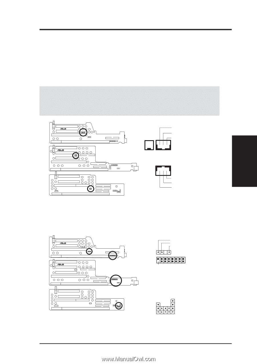
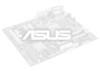
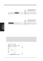
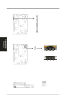
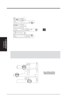
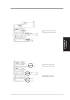
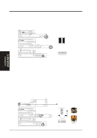
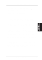
3. H/W SETUP Connectors 3. HARDWARE SETUP 2) LAN Activity Connectors (2-pin LAN_LED & 3-pin WOL_CON) These connectors support Local Area Network (LAN) cards, such as the ASUS PCI-L101 (see 7.1 PCI-L101 Fast Ethernet Card) with output signals for data transfer activity. The LAN_LED connector allows the front panel LED to flash during transfer activity between the network and the computer. The WOL_CON connector allows the system to power up when there is a wakeup package (signal) received from the network. IMPORTANT: This feature requires that Wake On LAN is set to Enabled (see 4.6 Power Management Setup) and that your system has an NLX power supply with at least 720mA +5V standby power. ® NLX-R ® B9-N NLX-R (Front) + LAN_LED (NLX-R only) B9-N (Front) +5 Volt Standby Ground PME WOL_CON NLX-R & Yeong-Yang Risers YEONG-YANG Yeong-Yang (Front) LAN Activity Connectors +5 Volt Standby Ground PME B9-N Riser 3) Front Panel Connector (16-1 pins) This connector is used to connect the front panel display LEDs and buttons to the motherboard through a ribbon cable. ® NLX-R ® B9-N NLX-R (Front) FCON B9-N (Front) LED_CTRL Right Audio Channel Left Audio Channel Ground 1 4 Pin 1 The front panel display & buttons connect to the riser card through a ribbon cable. 1 +Speaker-Connector - Power Switch - Reset Switch - HDD LED - Power LED YEONG-YANG Yeong-Yang (Front) Front Panel Display and Button Connector 1+ + + + ASUS P2B-N User's Manual 37
-
 1
1 -
2
-
3
-
4
-
5
-
6
-
7
-
8
-
9
-
10
-
11
-
12
-
13
-
14
-
15
-
16
-
17
-
18
-
19
-
20
-
21
-
22
-
23
-
24
-
25
-
26
-
27
-
28
-
29
-
30
-
31
-
 32
32 -
 33
33 -
 34
34 -
 35
35 -
 36
36 -
 37
37 -
 38
38 -
 39
39 -
 40
40 -
 41
41 -
 42
42 -
43
-
44
-
45
-
46
-
47
-
48
-
49
-
50
-
51
-
52
-
53
-
54
-
55
-
56
-
57
-
58
-
59
-
60
-
61
-
62
-
63
-
64
-
65
-
66
-
67
-
68
-
69
-
70
-
71
-
72
-
73
-
74
-
75
-
76
-
77
-
78
-
79
-
80
-
81
-
82
-
83
-
84
-
85
-
86
-
87
-
88
-
89
-
90
-
91
-
92
-
93
-
94
-
95
-
96
-
97
-
98
-
99
-
100
-
101
-
102
-
103
-
104
-
105
-
106
-
107
-
108
-
109
-
110
-
111
-
112
-
113
-
114
-
115
-
116
-
117
-
118
-
119
-
120
 |
 |