Asus P2B-N P2B-N User Manual - Page 34
Midboard Connectors - p2b cpu compatibility
 |
View all Asus P2B-N manuals
Add to My Manuals
Save this manual to your list of manuals |
Page 34 highlights
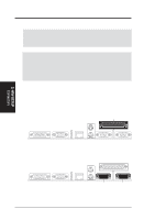
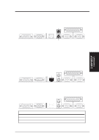
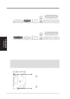
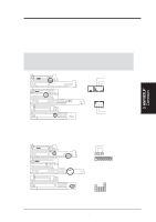
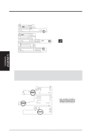
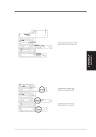
3. H/W SETUP Connectors 3. HARDWARE SETUP 7) Monitor Connector (15-pin VGA) This connector is for displaying on a standard VGA-compatible device. VGA Monitor (15-pin female) 8) Joystick/MIDI Connector (15-pin GAME) This connector is for a standard joystick or MIDI device. Joystick/Midi (15-pin female) 3.8.2 Midboard Connectors 1) CPU Fan Connector (3-pin CHASIS_FAN, 3-pin CPU_FAN) These connectors support cooling fans of 500mA (6 Watts) or less. Orientate the fans so that the heat sink fins allow airflow to go across the onboard heat sink(s) instead of the expansion slots. Depending on the fan manufacturer, the wiring and plug may be different. The red wire should be positive, while the black should be ground. Connect the fan's plug to the board taking into consideration the polarity of the this connector. NOTE: The "Rotation" signal is to be used only by a specially designed fan with rotation signal. WARNING! The CPU and/or motherboard will overheat if there is no airflow across the CPU and onboard heatsinks. Damage may occur to the motherboard and/or the CPU fan if these pins are incorrectly used. These are not jumpers, do not place jumper caps over these pins. CPU Fan Power Rotation +12 Volt Ground R Rotation +12 Volt Ground Chassis Fan Power P2B-N 12-Volt Cooling Fan Power 34 ASUS P2B-N User's Manual
-
 1
1 -
2
-
3
-
4
-
5
-
6
-
7
-
8
-
9
-
10
-
11
-
12
-
13
-
14
-
15
-
16
-
17
-
18
-
19
-
20
-
21
-
22
-
23
-
24
-
25
-
26
-
27
-
28
-
 29
29 -
 30
30 -
 31
31 -
 32
32 -
 33
33 -
 34
34 -
 35
35 -
 36
36 -
 37
37 -
 38
38 -
 39
39 -
40
-
41
-
42
-
43
-
44
-
45
-
46
-
47
-
48
-
49
-
50
-
51
-
52
-
53
-
54
-
55
-
56
-
57
-
58
-
59
-
60
-
61
-
62
-
63
-
64
-
65
-
66
-
67
-
68
-
69
-
70
-
71
-
72
-
73
-
74
-
75
-
76
-
77
-
78
-
79
-
80
-
81
-
82
-
83
-
84
-
85
-
86
-
87
-
88
-
89
-
90
-
91
-
92
-
93
-
94
-
95
-
96
-
97
-
98
-
99
-
100
-
101
-
102
-
103
-
104
-
105
-
106
-
107
-
108
-
109
-
110
-
111
-
112
-
113
-
114
-
115
-
116
-
117
-
118
-
119
-
120
 |
 |
