Asus P2B98-XV P2B98-XV User Manual - Page 13
Jumpers
 |
View all Asus P2B98-XV manuals
Add to My Manuals
Save this manual to your list of manuals |
Page 13 highlights
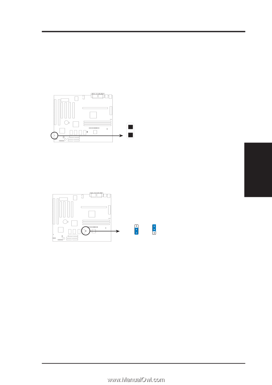
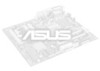
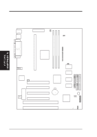
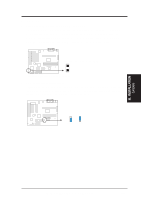
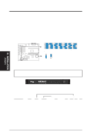
III. INSTALLATION 1. Jumpers 1. Clear Real Time Clock (RTC) RAM (CLRTC) The CMOS RAM is powered by the onboard button cell battery. To clear the RTC data: (1) Turn off your computer and uplug its AC power, (2) Short the two solder points labeled CLRTC, (3) Turn on your computer, (4) Hold down during bootup and enter BIOS setup to re-enter user preferences. Short the solder points to clear CMOS P2B98-XV Real Time Clock RAM (CLRTC) 2. VGA Interrupt Selection (INT) These jumpers allow you to set the VGA interrupt method. The default disables the chipset's internal interrupt routing. Some video capture cards may require that the interrupt be assigned by the onboard chipset. P2B98-XV VGA Interrupt INT 1 2 3 Enabled INT 1 2 3 Disabled III. INSTALLATION Jumpers ASUS P2B98-XV User's Manual 13
-
 1
1 -
2
-
3
-
4
-
5
-
6
-
7
-
 8
8 -
 9
9 -
 10
10 -
 11
11 -
 12
12 -
 13
13 -
 14
14 -
 15
15 -
 16
16 -
 17
17 -
 18
18 -
19
-
20
-
21
-
22
-
23
-
24
-
25
-
26
-
27
-
28
-
29
-
30
-
31
-
32
-
33
-
34
-
35
-
36
-
37
-
38
-
39
-
40
-
41
-
42
-
43
-
44
-
45
-
46
-
47
-
48
-
49
-
50
-
51
-
52
-
53
-
54
-
55
-
56
-
57
-
58
-
59
-
60
-
61
-
62
-
63
-
64
-
65
-
66
-
67
-
68
-
69
-
70
-
71
-
72
-
73
-
74
-
75
-
76
-
77
-
78
-
79
-
80
-
81
-
82
-
83
-
84
-
85
-
86
-
87
-
88
 |
 |