Asus P2B98-XV P2B98-XV User Manual - Page 28
ATX Power Supply Connector
 |
View all Asus P2B98-XV manuals
Add to My Manuals
Save this manual to your list of manuals |
Page 28 highlights
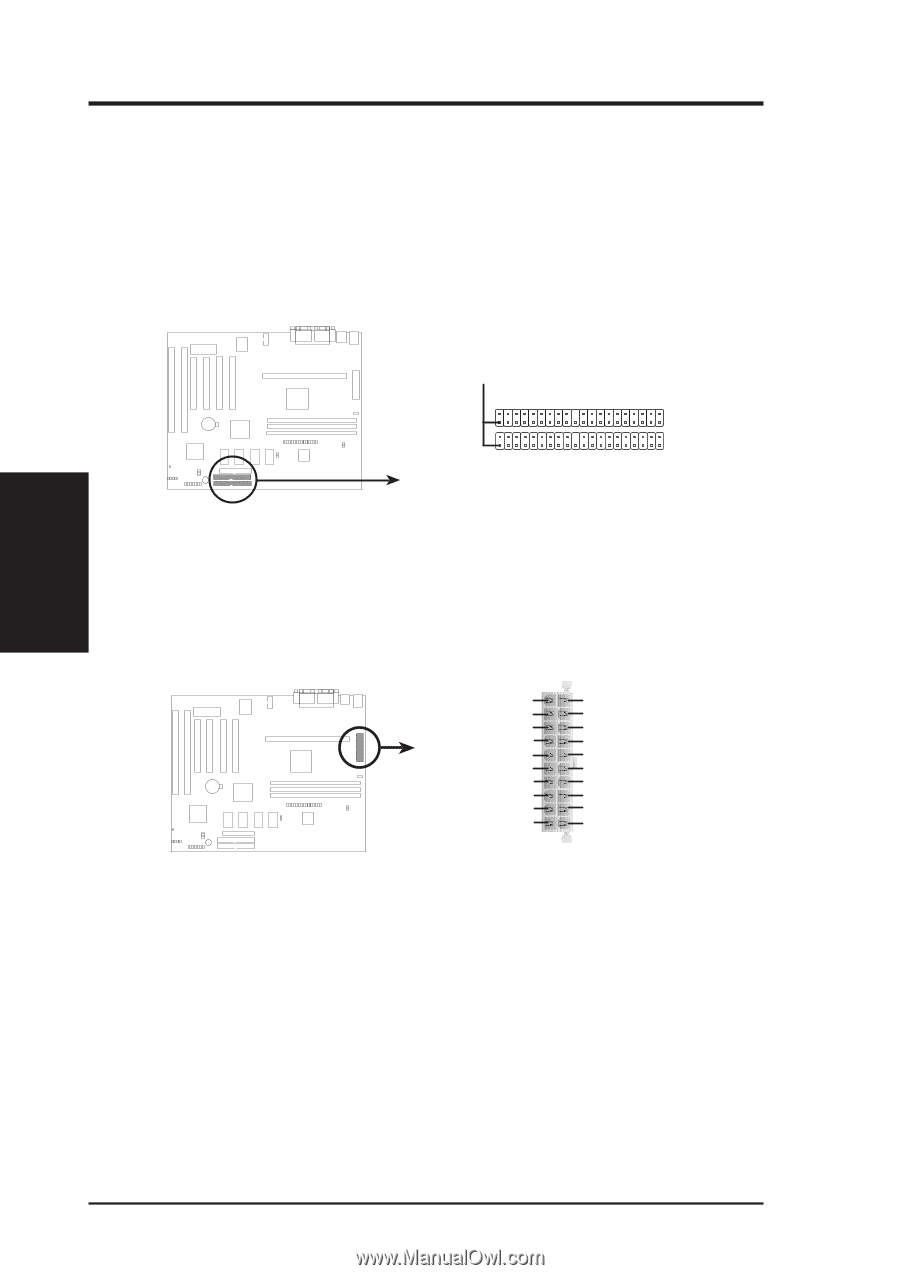
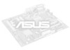
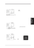
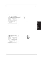
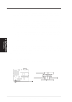
III. INSTALLATION Connectors III. INSTALLATION 10. Primary / Secondary IDE Connectors (Two 40-1pin IDE) These connectors support the provided IDE hard disk ribbon cable. After connecting the single end to the board, connect the two plugs at the other end to your hard disk(s). If you install two hard disks, you must configure the second drive to Slave mode by setting its jumper accordingly. Please refer to the documentation of your hard disk for the jumper settings. (Pin 20 is removed to prevent inserting in the wrong orientation when using ribbon cables with pin 20 plugged). NOTE: Orient the red stripe to Pin 1 Pin 1 Secondary IDE Connector Primary IDE Connector P2B98-XV IDE Connectors 11. ATX Power Supply Connector (20-pin ATXPWR) This connector connects to a ATX power supply. The plug from the power supply will only insert in one orientation because of the different hole sizes. Find the proper orientation and push down firmly making sure that the pins are aligned. +12.0 Volts +5V Standby Power Good Ground +5.0 Volts Ground +5.0 Volts Ground +3.3 Volts +3.3 Volts +5.0 Volts +5.0 Volts -5.0 Volts Ground Ground Ground Power Supply On Ground -12.0 Volts +3.3 Volts P2B98-XV ATX Power Connector IMPORTANT: Be sure that the ATX power supply can take at least 10mAmp load on the 5volt standby lead (+5VSB). You may experience difficulty in powering on your system without this. 28 ASUS P2B98-XV User's Manual
-
 1
1 -
2
-
3
-
4
-
5
-
6
-
7
-
8
-
9
-
10
-
11
-
12
-
13
-
14
-
15
-
16
-
17
-
18
-
19
-
20
-
21
-
22
-
 23
23 -
 24
24 -
 25
25 -
 26
26 -
 27
27 -
 28
28 -
 29
29 -
 30
30 -
 31
31 -
 32
32 -
 33
33 -
34
-
35
-
36
-
37
-
38
-
39
-
40
-
41
-
42
-
43
-
44
-
45
-
46
-
47
-
48
-
49
-
50
-
51
-
52
-
53
-
54
-
55
-
56
-
57
-
58
-
59
-
60
-
61
-
62
-
63
-
64
-
65
-
66
-
67
-
68
-
69
-
70
-
71
-
72
-
73
-
74
-
75
-
76
-
77
-
78
-
79
-
80
-
81
-
82
-
83
-
84
-
85
-
86
-
87
-
88
 |
 |