Asus P3PH4 P3-PH4 User''s Manual for English Edition - Page 30
Installing an optical drive
 |
View all Asus P3PH4 manuals
Add to My Manuals
Save this manual to your list of manuals |
Page 30 highlights
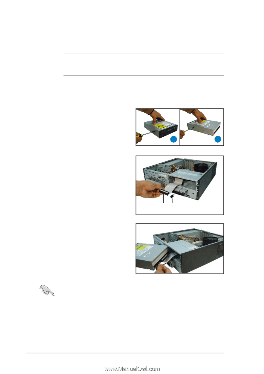
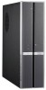
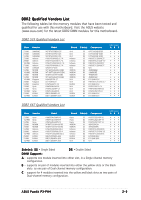
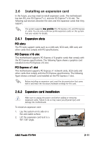
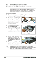
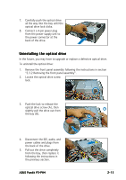
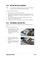
2.7 Installing an optical drive The system comes with a 5.25-inch drive bay for an optical drive. If you plan to install an IDE hard disk drive, set the optical drive as a slave device before installing it to the system. Refer to the optical drive documentation for details on how to set the drive as slave device. To install an optical drive: 1. Remove the front panel assembly following the instructions in section "2.3.2 Removing the front panel assembly." 2. Drive a screw on the top right screw hole on both sides of the drive. The screw holes are approximately 5 cm from the drive front panel and 2 cm from the drive base. 2 2 3. Lay the system on its side in a flat and stable surface. 4. Carefully pull the IDE and audio cables and plugs out from the bay until the cables are long enough to connect to the drive. IDE cable Audio cable and plug and plug 5. Connect the IDE cable to the IDE interface at the back of the drive. Match the red stripe on the cable with Pin 1 on the IDE interface. 6. Connect the optical drive audio cable to the 4-pin connector at the back of the optical drive. The IDE and audio plugs are pre-connected to the primary IDE and internal audio connectors on the motherboard. If you disconnected these plugs, refer to page 4-4 and 4-6 for their respective locations. 2-14 Chapter 2: Basic installation
-
 1
1 -
2
-
3
-
4
-
5
-
6
-
7
-
8
-
9
-
10
-
11
-
12
-
13
-
14
-
15
-
16
-
17
-
18
-
19
-
20
-
21
-
22
-
23
-
24
-
 25
25 -
 26
26 -
 27
27 -
 28
28 -
 29
29 -
 30
30 -
 31
31 -
 32
32 -
 33
33 -
 34
34 -
 35
35 -
36
-
37
-
38
-
39
-
40
-
41
-
42
-
43
-
44
-
45
-
46
-
47
-
48
-
49
-
50
-
51
-
52
-
53
-
54
-
55
-
56
-
57
-
58
-
59
-
60
-
61
-
62
-
63
-
64
-
65
-
66
-
67
-
68
-
69
-
70
-
71
-
72
-
73
-
74
-
75
-
76
-
77
-
78
-
79
-
80
-
81
-
82
-
83
-
84
-
85
-
86
-
87
-
88
-
89
-
90
-
91
-
92
-
93
-
94
-
95
-
96
 |
 |