Asus P3PH4 P3-PH4 User''s Manual for English Edition - Page 52
Connectors
 |
View all Asus P3PH4 manuals
Add to My Manuals
Save this manual to your list of manuals |
Page 52 highlights
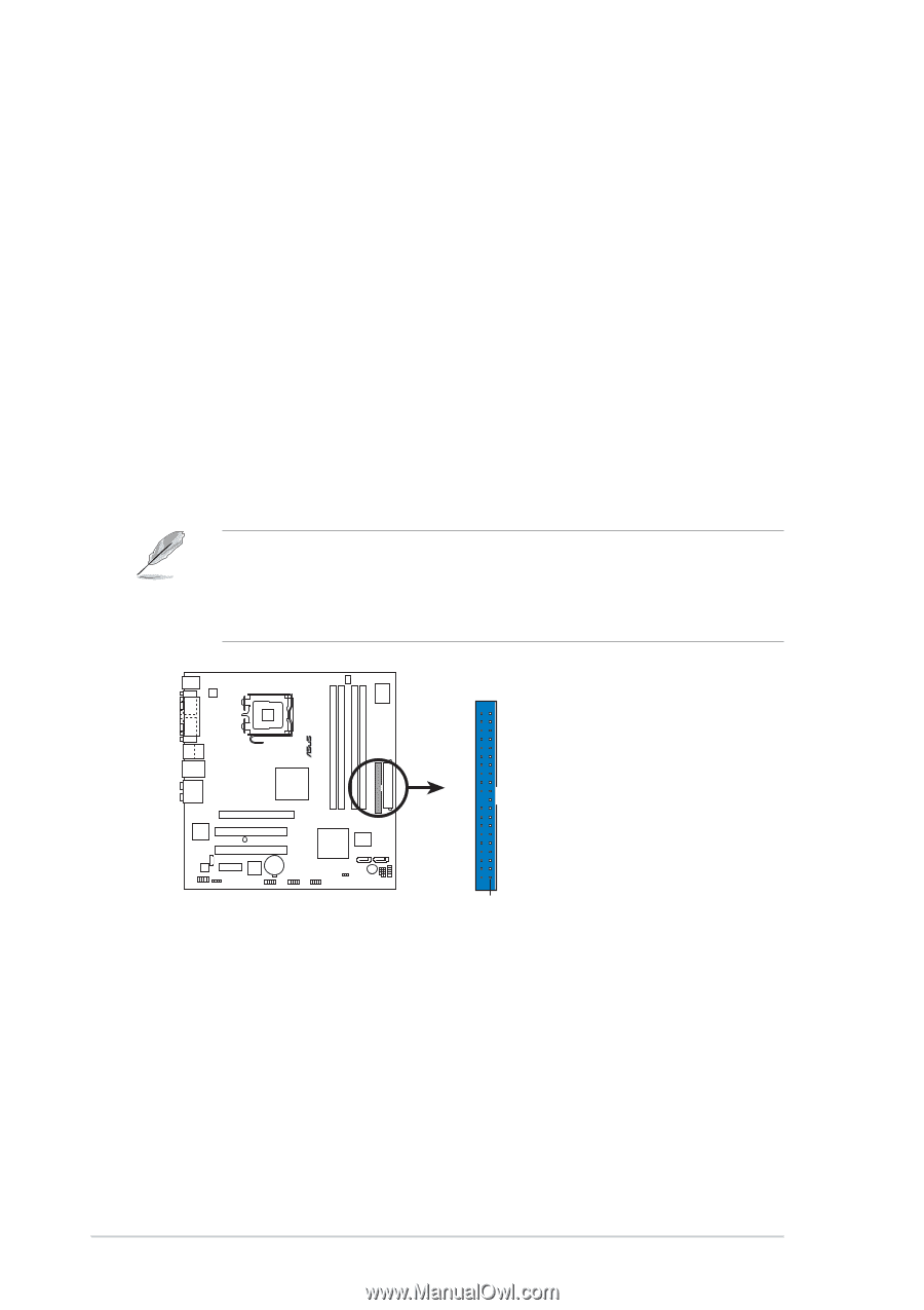
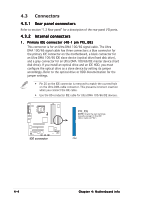
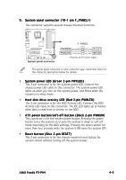
4.3 Connectors 4.3.1 Rear panel connectors Refer to section "1.3 Rear panel" for a description of the rear panel I/O ports. 4.3.2 Internal connectors 1 . Primary IDE connector (40-1 pin PRI_IDE) This connector is for an Ultra DMA 100/66 signal cable. The Ultra DMA 100/66 signal cable has three connectors: a blue connector for the primary IDE connector on the motherboard, a black connector for an Ultra DMA 100/66 IDE slave device (optical drive/hard disk drive), and a gray connector for an Ultra DMA 100/66 IDE master device (hard disk drive). If you install an optical drive and an IDE HDD, you must configure the optical drive as a slave device by setting its jumper accordingly. Refer to the optical drive or HDD documentation for the jumper settings. • Pin 20 on the IDE connector is removed to match the covered hole on the Ultra DMA cable connector. This prevents incorrect insertion when you connect the IDE cable. • Use the 80-conductor IDE cable for Ultra DMA 100/66 IDE devices. PRI_IDE NOTE: Orient the red markings (usually zigzag) on the IDE ribbon cable to PIN 1. ® IDE connector PIN 1 4-4 Chapter 4: Motherboard info
-
 1
1 -
2
-
3
-
4
-
5
-
6
-
7
-
8
-
9
-
10
-
11
-
12
-
13
-
14
-
15
-
16
-
17
-
18
-
19
-
20
-
21
-
22
-
23
-
24
-
25
-
26
-
27
-
28
-
29
-
30
-
31
-
32
-
33
-
34
-
35
-
36
-
37
-
38
-
39
-
40
-
41
-
42
-
43
-
44
-
45
-
46
-
 47
47 -
 48
48 -
 49
49 -
 50
50 -
 51
51 -
 52
52 -
 53
53 -
 54
54 -
 55
55 -
 56
56 -
 57
57 -
58
-
59
-
60
-
61
-
62
-
63
-
64
-
65
-
66
-
67
-
68
-
69
-
70
-
71
-
72
-
73
-
74
-
75
-
76
-
77
-
78
-
79
-
80
-
81
-
82
-
83
-
84
-
85
-
86
-
87
-
88
-
89
-
90
-
91
-
92
-
93
-
94
-
95
-
96
 |
 |