Asus P5VDC-MX V2.0 Motherboard DIY Troubleshooting Guide - Page 39
Primary/Secondary IDE connector 40-1 pin PRI_IDE
 |
View all Asus P5VDC-MX V2.0 manuals
Add to My Manuals
Save this manual to your list of manuals |
Page 39 highlights
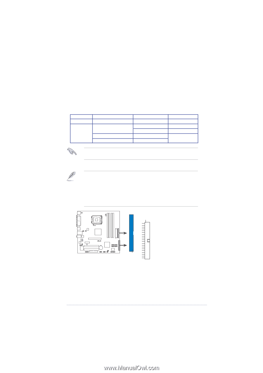
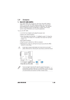
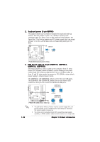
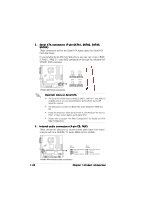
2. Primary/Secondary IDE connector (40-1 pin PRI_IDE, SEC_IDE) The onboard IDE connectors are for Ultra DMA 133/100/66 signal cables. There are three connectors on each Ultra DMA 133/100/66 signal cable: blue, black, and gray. Connect the blue connector to the motherboard's IDE connector, and then select one of the following modes to configure your device. Single device Two devices Drive jumper setting Cable-Select or Master Cable-Select Master Slave Mode of derve(s) Master Slave Master Slave Cable connector black black gray black or gray If any device jumper is set as "Cable-Select, " make sure all other device jumpers have the same settng. 1. Follow the hard disk drive documentation when setting the device in master or slave mode. 2. Pin 20 on each IDE connector is removed to match the covered hole on the UltraATA cable connector. This prevents incorrect orientation when you connect the cables. 3. The hole near the blue connector on the UltraATA cable is intentional. NOTE: Orient the red markings PIN 1 (usually zigzag) on the IDE ribbon cable to PIN 1. P5VDC-MX PRI_IDE SEC_IDE ® PIN 1 P5VDC-MX IDE connectors ASUS P5VDC-MX 1-27
-
 1
1 -
2
-
3
-
4
-
5
-
6
-
7
-
8
-
9
-
10
-
11
-
12
-
13
-
14
-
15
-
16
-
17
-
18
-
19
-
20
-
21
-
22
-
23
-
24
-
25
-
26
-
27
-
28
-
29
-
30
-
31
-
32
-
33
-
 34
34 -
 35
35 -
 36
36 -
 37
37 -
 38
38 -
 39
39 -
 40
40 -
 41
41 -
 42
42 -
 43
43 -
 44
44 -
45
-
46
-
47
-
48
-
49
-
50
-
51
-
52
-
53
-
54
-
55
-
56
-
57
-
58
-
59
-
60
-
61
-
62
-
63
-
64
-
65
-
66
-
67
-
68
-
69
-
70
-
71
-
72
-
73
-
74
-
75
-
76
-
77
-
78
-
79
-
80
-
81
-
82
-
83
-
84
-
85
-
86
-
87
-
88
-
89
-
90
-
91
-
92
-
93
-
94
 |
 |