Asus PR-DLSR PR-DLSR User Manual - Page 22
These two 4-pin Universal Serial Bus USB ports
 |
View all Asus PR-DLSR manuals
Add to My Manuals
Save this manual to your list of manuals |
Page 22 highlights
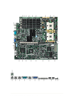
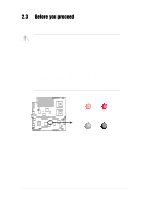
20 8-switch DIP (SW2). This 8-switch Dual Inline Package (DIP) allows you to select the CPU frequency multiple. 21 64-bit 133/100MHz PCI slot. This PCI expansion slot is for the proprietary riser card with dual PCI-X slots. The PCI-X slots support bus master PCI-X/PCI cards. 22 PS/2 mouse port. This green 6-pin connector is for a PS/2 mouse. 23 PS/2 keyboard port. This purple 6-pin connector is for a PS/2 keyboard. 24 RJ-45 port (100/10 Mbps). This port allows connection to a Local Area Network (LAN) through a network hub to support 10BASE-T/ 100BASE-TX networking protocols. 25 RJ-45 port (1000/100/10 Mbps). This port allows connection to a Local Area Network (LAN) through a network hub to support up to 1000Mbps data transfer rates. 26 Serial port. This 9-pin COM1 port is for pointing devices or other serial devices. 27 RJ-45 port (for server management). This port allows connection to a Local Area Network (LAN) through a network hub to support the remote power management feature. 28 VGA port. This port is for a VGA-monitor or other VGA-compatible devices. 29 SCSI LED. This LED indicates the status of the SCSI device connected to the external SCSI connector. 30 High-density SCSI connector. This dual-channel 68-pin Ultra-160/ 320 SCSI connector supports up to 30 SCSI devices, and data transfers of 160Mbps/320Mbps. 31 USB 1.1 ports. These two 4-pin Universal Serial Bus (USB) ports are available for connecting USB devices. 32 Location switch. Pressing this switch causes the location LED to light up, allowing you to locate a specific 1U system when several system are installed in a rack. This switch has a counterpart on the front panel. When you press either the front or rear panel location switch, the location LED on both the front and rear panels light up. 33 Location LED. This LED indicates the specific 1U system installed on a rack. 1-10 Chapter 1: Product introduction
-
 1
1 -
2
-
3
-
4
-
5
-
6
-
7
-
8
-
9
-
10
-
11
-
12
-
13
-
14
-
15
-
16
-
 17
17 -
 18
18 -
 19
19 -
 20
20 -
 21
21 -
 22
22 -
 23
23 -
 24
24 -
 25
25 -
 26
26 -
 27
27 -
28
-
29
-
30
-
31
-
32
-
33
-
34
-
35
-
36
-
37
-
38
-
39
-
40
-
41
-
42
-
43
-
44
-
45
-
46
-
47
-
48
-
49
-
50
-
51
-
52
-
53
-
54
-
55
-
56
-
57
-
58
-
59
-
60
-
61
-
62
-
63
-
64
-
65
-
66
-
67
-
68
-
69
-
70
-
71
-
72
-
73
-
74
-
75
-
76
-
77
-
78
-
79
-
80
-
81
-
82
-
83
-
84
-
85
-
86
-
87
-
88
-
89
-
90
-
91
-
92
-
93
-
94
-
95
-
96
-
97
-
98
-
99
-
100
-
101
-
102
-
103
-
104
-
105
-
106
 |
 |