Asus PR-DLSR PR-DLSR User Manual - Page 41
Connectors
 |
View all Asus PR-DLSR manuals
Add to My Manuals
Save this manual to your list of manuals |
Page 41 highlights
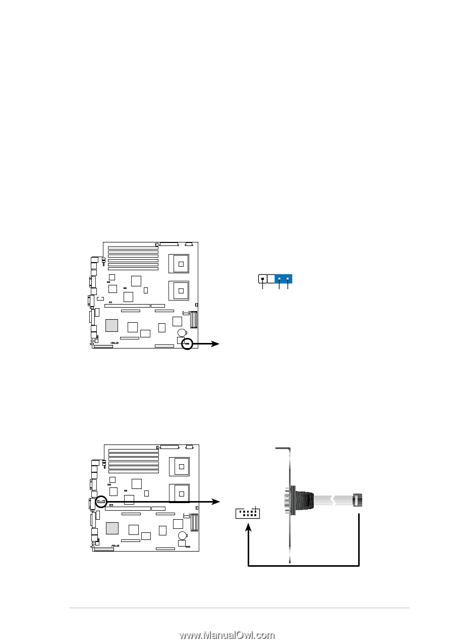
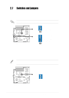
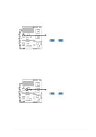
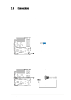
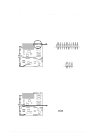
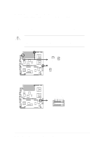
2.8 Connectors This section describes and illustrates the internal connectors on the motherboard. 1. Chassis alarm lead (4-1 pin CHASSIS) This lead is for a chassis designed with intrusion detection feature. This requires an external detection mechanism such as a chassis intrusion sensor or microswitch. When you remove any chassis component, the sensor triggers and sends a high-level signal to this lead to record a chassis intrusion event. By default, the pins labeled "Chassis Signal" and "Ground" are shorted with a jumper cap. If you wish to use the chassis intrusion detection feature, remove the jumper cap from the pins. CHASSIS +5Volt (Power Supply Stand By) Chassis Signal Ground PR-DLSR ® PR-DLSR Chassis Open Alarm Lead 2. Serial port 2 connector (10-1 pin COM2) This connector accommodates a second serial port using an optional serial port bracket. Connect the bracket cable to this connector then install the bracket into a slot opening at the back of the system chassis. COM2 PIN 1 PR-DLSR ® PR-DLSR Serial COM2 Connector ASUS PR-DLSR motherboard user guide 2-17
-
 1
1 -
2
-
3
-
4
-
5
-
6
-
7
-
8
-
9
-
10
-
11
-
12
-
13
-
14
-
15
-
16
-
17
-
18
-
19
-
20
-
21
-
22
-
23
-
24
-
25
-
26
-
27
-
28
-
29
-
30
-
31
-
32
-
33
-
34
-
35
-
 36
36 -
 37
37 -
 38
38 -
 39
39 -
 40
40 -
 41
41 -
 42
42 -
 43
43 -
 44
44 -
 45
45 -
 46
46 -
47
-
48
-
49
-
50
-
51
-
52
-
53
-
54
-
55
-
56
-
57
-
58
-
59
-
60
-
61
-
62
-
63
-
64
-
65
-
66
-
67
-
68
-
69
-
70
-
71
-
72
-
73
-
74
-
75
-
76
-
77
-
78
-
79
-
80
-
81
-
82
-
83
-
84
-
85
-
86
-
87
-
88
-
89
-
90
-
91
-
92
-
93
-
94
-
95
-
96
-
97
-
98
-
99
-
100
-
101
-
102
-
103
-
104
-
105
-
106
 |
 |