Asus PR-DLSR PR-DLSR User Manual - Page 35
Configuring an expansion card
 |
View all Asus PR-DLSR manuals
Add to My Manuals
Save this manual to your list of manuals |
Page 35 highlights
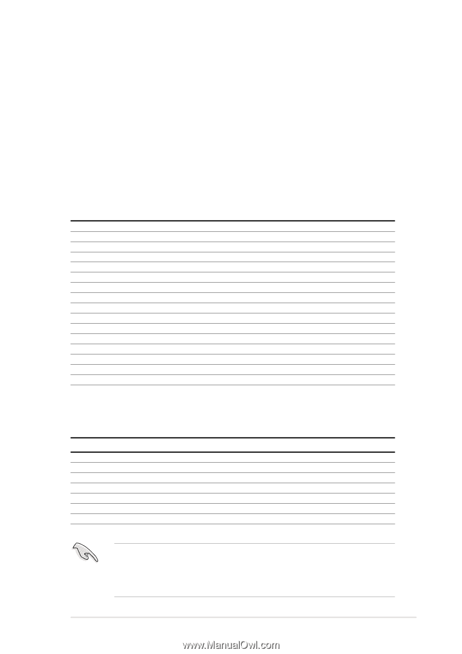
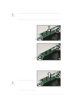
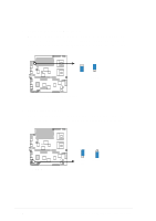
2.6.2 Configuring an expansion card After installing the expansion card, configure the it by adjusting the software settings. 1. Turn on the system and change the necessary BIOS settings, if any. See Chapter 4 for information on BIOS setup. 2. Assign an IRQ to the card. Refer to the tables on the next page. 3. Install the software drivers for the expansion card. Standard Interrupt Assignments IRQ Priority Standard Function 0 1 System Timer 1 2 Keyboard Controller 2 N/A Programmable Interrupt 3* 11 Communications Port (COM2) 4* 12 Communications Port (COM1) 5* 13 Sound Card (sometimes LPT2) 6 14 Floppy Disk Controller 7* 15 Printer Port (LPT1) 8 3 System CMOS/Real Time Clock 9* 4 ACPI Mode when used 10* 5 IRQ Holder for PCI Steering 11* 6 IRQ Holder for PCI Steering 12* 7 PS/2 Compatible Mouse Port 13 8 Numeric Data Processor 14* 9 Primary IDE Channel 15* 10 Secondary IDE Channel * These IRQs are usually available for ISA or PCI devices. PCI interrupt assignments for this motherboard 82551QM LAN controller 82544GC LAN controller SCSI controller VGA controller ASMB PCI slot1 on the riser card PCI slot2 on the riser card A B C D 2 - - - 8 - - - 9 10 - - 1 - - - 3 4 17 18 5 13 14 15 6 15 13 14 When using PCI cards on shared slots, ensure that the drivers support "Share IRQ" or that the cards do not need IRQ assignments. Otherwise, conflicts will arise between the two PCI groups, making the system unstable and the card inoperable. ASUS PR-DLSR motherboard user guide 2-11
-
 1
1 -
2
-
3
-
4
-
5
-
6
-
7
-
8
-
9
-
10
-
11
-
12
-
13
-
14
-
15
-
16
-
17
-
18
-
19
-
20
-
21
-
22
-
23
-
24
-
25
-
26
-
27
-
28
-
29
-
 30
30 -
 31
31 -
 32
32 -
 33
33 -
 34
34 -
 35
35 -
 36
36 -
 37
37 -
 38
38 -
 39
39 -
 40
40 -
41
-
42
-
43
-
44
-
45
-
46
-
47
-
48
-
49
-
50
-
51
-
52
-
53
-
54
-
55
-
56
-
57
-
58
-
59
-
60
-
61
-
62
-
63
-
64
-
65
-
66
-
67
-
68
-
69
-
70
-
71
-
72
-
73
-
74
-
75
-
76
-
77
-
78
-
79
-
80
-
81
-
82
-
83
-
84
-
85
-
86
-
87
-
88
-
89
-
90
-
91
-
92
-
93
-
94
-
95
-
96
-
97
-
98
-
99
-
100
-
101
-
102
-
103
-
104
-
105
-
106
 |
 |