Asus RS260-E4 RX8 Service Guide - Page 46
Cable connections
 |
View all Asus RS260-E4 RX8 manuals
Add to My Manuals
Save this manual to your list of manuals |
Page 46 highlights
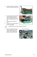
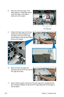
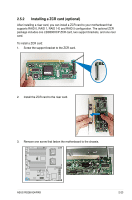
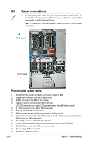
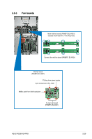
2.6 Cable connections • The bundled system cables are pre-connected before shipment. You do not need to disconnect these cables unless you will remove pre-installed components to install additional devices. • Refer to this section when reconnecting cables to ensure correct cable connections. Rear panel 12 1 13 11 2 9 4 6 35 7 Front panel 8 10 Pre-connected system cables 1. 24-pin/8-pin/4pin power connectors (from power supply to MB) 2. Floppy drive connector (from MB to floppy drive) 3. PANEL connectors (from MB to front panel) 4. Chassis intrusion connector (from MB to chassis) LAN LED connector and Locator LED connector/switch (from MB to front panel) 5. 2 x SAS connectors (from MB to SAS backplane) 6. Primary IDE (from MB to optical drive) 7. Mid-fan power connector (from power supply to mid-fan board) 8. SAS board connectors (from the SAS backplane to MB and power supply; one from the Mid-fan board to SAS backplane) 9. Front USB connectors (from MB to front panel) 10. Locator LED connector/switch (from front panel to rear panel Locator LED/switch) 11. CPU_FAN1 connector (from MB to mid-fan board) 12. Power supply SMBus connector 13. Backplane SMBus connector 2-26 Chapter 2: Hardware setup
-
 1
1 -
2
-
3
-
4
-
5
-
6
-
7
-
8
-
9
-
10
-
11
-
12
-
13
-
14
-
15
-
16
-
17
-
18
-
19
-
20
-
21
-
22
-
23
-
24
-
25
-
26
-
27
-
28
-
29
-
30
-
31
-
32
-
33
-
34
-
35
-
36
-
37
-
38
-
39
-
40
-
 41
41 -
 42
42 -
 43
43 -
 44
44 -
 45
45 -
 46
46 -
 47
47 -
 48
48 -
 49
49 -
 50
50 -
 51
51 -
52
-
53
-
54
-
55
-
56
-
57
-
58
-
59
-
60
-
61
-
62
-
63
-
64
-
65
-
66
-
67
-
68
-
69
-
70
-
71
-
72
-
73
-
74
-
75
-
76
-
77
-
78
-
79
-
80
-
81
-
82
-
83
-
84
-
85
-
86
-
87
-
88
-
89
-
90
-
91
-
92
-
93
-
94
-
95
-
96
-
97
-
98
-
99
-
100
-
101
-
102
-
103
-
104
-
105
-
106
-
107
-
108
-
109
-
110
-
111
-
112
-
113
-
114
-
115
-
116
-
117
-
118
-
119
-
120
-
121
-
122
-
123
-
124
-
125
-
126
-
127
-
128
-
129
-
130
-
131
-
132
-
133
-
134
-
135
-
136
-
137
-
138
-
139
-
140
-
141
-
142
-
143
-
144
-
145
-
146
-
147
-
148
-
149
-
150
-
151
-
152
-
153
-
154
-
155
-
156
-
157
-
158
-
159
-
160
-
161
-
162
-
163
-
164
-
165
-
166
-
167
-
168
-
169
-
170
-
171
-
172
-
173
-
174
-
175
-
176
-
177
-
178
-
179
-
180
-
181
-
182
 |
 |
