Asus RS260-E4 RX8 Service Guide - Page 54
Front panel LED and switch board
 |
View all Asus RS260-E4 RX8 manuals
Add to My Manuals
Save this manual to your list of manuals |
Page 54 highlights
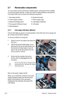
2.7.4 Front panel LED and switch board To uninstall the front panel and swtich board: 1. Disconnect all cables connected to the rear of the board. 2. Remove sticker on the front panel and unscrew the board to the chassis. 3. Carefully remove the board out of the chassis. When removed, the LED and switch board appears as shown. The LEDs and switches on the board correspond to the LEDs and buttons on the system front panel. Locator LED connector (red/black) Locator switch connector (blue/white) Panel connector Front USB connector Front side Rear side 2-34 Chapter 2: Hardware setup
-
 1
1 -
2
-
3
-
4
-
5
-
6
-
7
-
8
-
9
-
10
-
11
-
12
-
13
-
14
-
15
-
16
-
17
-
18
-
19
-
20
-
21
-
22
-
23
-
24
-
25
-
26
-
27
-
28
-
29
-
30
-
31
-
32
-
33
-
34
-
35
-
36
-
37
-
38
-
39
-
40
-
41
-
42
-
43
-
44
-
45
-
46
-
47
-
48
-
 49
49 -
 50
50 -
 51
51 -
 52
52 -
 53
53 -
 54
54 -
 55
55 -
 56
56 -
 57
57 -
 58
58 -
 59
59 -
60
-
61
-
62
-
63
-
64
-
65
-
66
-
67
-
68
-
69
-
70
-
71
-
72
-
73
-
74
-
75
-
76
-
77
-
78
-
79
-
80
-
81
-
82
-
83
-
84
-
85
-
86
-
87
-
88
-
89
-
90
-
91
-
92
-
93
-
94
-
95
-
96
-
97
-
98
-
99
-
100
-
101
-
102
-
103
-
104
-
105
-
106
-
107
-
108
-
109
-
110
-
111
-
112
-
113
-
114
-
115
-
116
-
117
-
118
-
119
-
120
-
121
-
122
-
123
-
124
-
125
-
126
-
127
-
128
-
129
-
130
-
131
-
132
-
133
-
134
-
135
-
136
-
137
-
138
-
139
-
140
-
141
-
142
-
143
-
144
-
145
-
146
-
147
-
148
-
149
-
150
-
151
-
152
-
153
-
154
-
155
-
156
-
157
-
158
-
159
-
160
-
161
-
162
-
163
-
164
-
165
-
166
-
167
-
168
-
169
-
170
-
171
-
172
-
173
-
174
-
175
-
176
-
177
-
178
-
179
-
180
-
181
-
182
 |
 |

Chapter 2:
Hardware setup
2-34
2.7.4
Front panel LED and switch board
To uninstall the front panel and swtich board:
1.
Disconnect all cables connected to the rear of the board.
2.
Remove sticker on the front panel and unscrew the board to the chassis.
Front side
Rear side
Locator switch connector (blue/white)
Panel connector
Front USB connector
Locator LED connector (red/black)
3.
Carefully remove the board out of the chassis.
When removed, the LED and switch board appears as shown. The LEDs and
switches on the board correspond to the LEDs and buttons on the system front
panel.