Asus T2-PE1 T2-PE1 English User Manual E2151 - Page 16

Audio ports function variation

Page 16 highlights

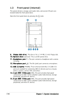
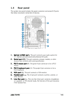
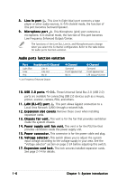
8 . L i n e I n p o r t . This Line In (light blue) port connects a tape player or other audio sources. In 4/6-channel mode, the function of this port becomes Surround Speaker. 9 . M i c r o p h o n e p o r t . This Microphone (pink) port connects a microphone. In 6-channel mode, the function of this port becomes Low Frequency Enhanced Output/Center. The functions of the Line Out, Line In, and Microphone ports change when you select the 6-channel configuration. Refer to the table below for audio ports function variation. Audio ports function variation Port Headphone/2-Channel Light Blue Lime Pink Line In Line Out Mic In * Low Frequency Enhanced Output 4-Channel Surround Front Speaker Out Mic In 6-Channel Surround Front Speaker Out LFE Output*/Center 1 0 . U S B 2 . 0 p o r t s 2.0. These Universal Serial Bus 2.0 (USB 2.0) ports are available for connecting USB 2.0 devices such as a mouse, printer, scanner, camera, PDA, and others. 1 1 . L A N ( R J - 4 5 ) p o r t . This port allows Gigabit connection to a Local Area Network (LAN) through a network hub. 1 2 . E x p a n s i o n s l o t c o v e r s. Remove these cover when installing expansion cards. 1 3 . C h a s s i s f a n v e n t . This vent is for the fan that provides ventilation inside the system chassis. 1 4 . P o w e r s u p p l y u n i t f a n v e n t . This vent is for the PSU fan that provides ventilation inside the power supply unit. 1 5 . P o w e r c o n n e c t o r . This connector is for the power cable and plug. 1 6 . V o l t a g e s e l e c t o r . This switch allows you to adjust the system input voltage according to the voltage supply in your area. See the "Voltage selector" section on page 2-24 before adjusting this switch. 1 7 . E x p a n s i o n c a r d l o c k . This lock secures installed expansion cards. See page 2-14 for details. 1-6 Chapter 1: System introduction

  • 1
  • 2
  • 3
  • 4
  • 5
  • 6
  • 7
  • 8
  • 9
  • 10
  • 11
  • 12
  • 13
  • 14
  • 15
  • 16
  • 17
  • 18
  • 19
  • 20
  • 21
  • 22
  • 23
  • 24
  • 25
  • 26
  • 27
  • 28
  • 29
  • 30
  • 31
  • 32
  • 33
  • 34
  • 35
  • 36
  • 37
  • 38
  • 39
  • 40
  • 41
  • 42
  • 43
  • 44
  • 45
  • 46
  • 47
  • 48
  • 49
  • 50
  • 51
  • 52
  • 53
  • 54
  • 55
  • 56
  • 57
  • 58
  • 59
  • 60
  • 61
  • 62
  • 63
  • 64
  • 65
  • 66
  • 67
  • 68
  • 69
  • 70
  • 71
  • 72
  • 73
  • 74
  • 75
  • 76
  • 77
  • 78
  • 79
  • 80
  • 81
  • 82
  • 83
  • 84
  • 85
  • 86
  • 87
  • 88
  • 89
  • 90
  • 91
  • 92
  • 93
  • 94
  • 95
  • 96
  • 97
  • 98
  • 99
  • 100
  • 101
  • 102
  • 103
  • 104
  • 105
  • 106
  • 107
  • 108
  • 109
  • 110

1-6
1-6
1-6
1-6
1-6
Chapter 1: System introduction
8.
8.
8.
8.
8.
Line In port
Line In port
Line In port
Line In port
Line In port
.
.
.
.
. This Line In (light blue) port connects a tape
player or other audio sources. In 4/6-channel mode, the function of
this port becomes Surround Speaker.
9.
9.
9.
9.
9.
Microphone port
Microphone port
Microphone port
Microphone port
Microphone port
.
.
.
.
. This Microphone (pink) port connects a
microphone. In 6-channel mode, the function of this port becomes
Low Frequency Enhanced Output/Center.
Audio ports function variation
10.
10.
10.
10.
10. USB 2.0 ports
USB 2.0 ports
USB 2.0 ports
USB 2.0 ports
USB 2.0 ports
2.0
.
.
.
.
. These Universal Serial Bus 2.0 (USB 2.0)
ports are available for connecting USB 2.0 devices such as a mouse,
printer, scanner, camera, PDA, and others.
11.
11.
11.
11.
11. LAN (RJ-45) port
LAN (RJ-45) port
LAN (RJ-45) port
LAN (RJ-45) port
LAN (RJ-45) port
.
.
.
.
. This port allows Gigabit connection to a
Local Area Network (LAN) through a network hub.
12.
12.
12.
12.
12. Expansion slot covers
Expansion slot covers
Expansion slot covers. Remove these cover when installing
expansion cards.
13.
13.
13.
13.
13. Chassis fan vent.
Chassis fan vent.
Chassis fan vent.
Chassis fan vent.
Chassis fan vent. This vent is for the fan that provides ventilation
inside the system chassis.
14.
14.
14.
14.
14. Power supply unit fan vent.
Power supply unit fan vent.
Power supply unit fan vent. This vent is for the PSU fan that
provides ventilation inside the power supply unit.
15.
15.
15.
15.
15. Power connector.
Power connector.
Power connector.
Power connector.
Power connector. This connector is for the power cable and plug.
16.
16.
16.
16.
16. Voltage selector.
Voltage selector.
Voltage selector.
Voltage selector.
Voltage selector. This switch allows you to adjust the system
input voltage according to the voltage supply in your area. See the
“Voltage selector” section on page 2-24 before adjusting this switch.
17.
17.
17.
17.
17. Expansion card lock.
Expansion card lock.
Expansion card lock. This lock secures installed expansion cards.
See page 2-14 for details.
The functions of the Line Out, Line In, and Microphone ports change
when you select the 6-channel configuration. Refer to the table below
for audio ports function variation.
* Low Frequency Enhanced Output
Port
Port
Port
Port
Port
Headphone/2-Channel
Headphone/2-Channel
Headphone/2-Channel
Headphone/2-Channel
Headphone/2-Channel
4-Channel
4-Channel
4-Channel
4-Channel
4-Channel
6-Channel
6-Channel
6-Channel
6-Channel
6-Channel
Light Blue
Line In
Surround
Surround
Lime
Line Out
Front Speaker Out
Front Speaker Out
Pink
Mic In
Mic In
LFE Output*/Center