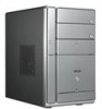
Asus T2-PE1 T2-PE1 English User Manual E2151 - Page 42
Voltage selector
 |
View all Asus T2-PE1 manuals
Add to My Manuals
Save this manual to your list of manuals |
Page 42 highlights
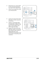
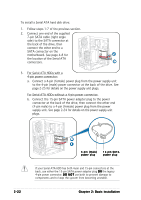
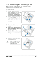
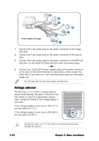
Power supply unit plugs 8 9 1 7 2 9 1 7. Connect the 4-pin power plug to the power connector of the floppy disk drive. 8. Connect the 4-pin power plug to the power connector of the optical drive. 9. Connect the 4-pin power plug to the power connector of the IDE hard disk drive, or the Serial ATA hard disk drive with 4-pin power plug. - or - 9. Connect the 15-pin SATA power adapter plug to the power connector at the back of the SATA hard disk or optical drive, then connect the other end (4-pin male) to a 4-pin (female) power plug from the power supply unit. See the Appendix for the power supply specifications. Voltage selector The PSU has a 115 V/230 V voltage selector switch located beside the power connector. Use this switch to select the appropriate system input voltage according to the voltage supply in your area. If the voltage supply in your area is 100-127 V, set the switch to 115 V. If the voltage supply in your area is 200-240 V, set the switch to 230 V. Setting the switch to 115 V in a 230 V environment will seriously damage the system! 2-24 Chapter 2: Basic installation
-
 1
1 -
2
-
3
-
4
-
5
-
6
-
7
-
8
-
9
-
10
-
11
-
12
-
13
-
14
-
15
-
16
-
17
-
18
-
19
-
20
-
21
-
22
-
23
-
24
-
25
-
26
-
27
-
28
-
29
-
30
-
31
-
32
-
33
-
34
-
35
-
36
-
 37
37 -
 38
38 -
 39
39 -
 40
40 -
 41
41 -
 42
42 -
 43
43 -
 44
44 -
 45
45 -
 46
46 -
 47
47 -
48
-
49
-
50
-
51
-
52
-
53
-
54
-
55
-
56
-
57
-
58
-
59
-
60
-
61
-
62
-
63
-
64
-
65
-
66
-
67
-
68
-
69
-
70
-
71
-
72
-
73
-
74
-
75
-
76
-
77
-
78
-
79
-
80
-
81
-
82
-
83
-
84
-
85
-
86
-
87
-
88
-
89
-
90
-
91
-
92
-
93
-
94
-
95
-
96
-
97
-
98
-
99
-
100
-
101
-
102
-
103
-
104
-
105
-
106
-
107
-
108
-
109
-
110
 |
 |
