Asus T2-PE1 T2-PE1 English User Manual E2151 - Page 64
Connectors
 |
View all Asus T2-PE1 manuals
Add to My Manuals
Save this manual to your list of manuals |
Page 64 highlights
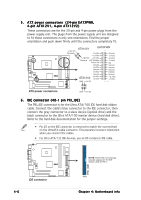
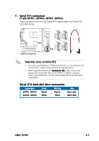
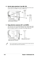
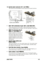
4.4 Connectors This section describes and illustrates the connectors on the motherboard. See page 1-7 for the description of rear panel connectors. 1 . Front panel audio connector (10-1 pin FP_AUDIO) This interface is for the FP_AUD connector on the front panel I/O daughterboard to support the front panel audio I/O ports. AGND +5VA BLINE_OUT_R BLINE_OUT_L ¤ Front panel audio connector FP_AUDIO MIC2 MICPWR Line out_R NC Line out_L 2 . Digital audio connector (4-1 pin SPDIF_OUT) (A) is for the SPDIF_OUT connector on the motherboard while (B) is for the rear panel S/PDIF Out port. ¤ Digital audio connector SPDIF_OUT GND SPDIFOUT +5V A B 4-4 Chapter 4: Motherboard info
-
 1
1 -
2
-
3
-
4
-
5
-
6
-
7
-
8
-
9
-
10
-
11
-
12
-
13
-
14
-
15
-
16
-
17
-
18
-
19
-
20
-
21
-
22
-
23
-
24
-
25
-
26
-
27
-
28
-
29
-
30
-
31
-
32
-
33
-
34
-
35
-
36
-
37
-
38
-
39
-
40
-
41
-
42
-
43
-
44
-
45
-
46
-
47
-
48
-
49
-
50
-
51
-
52
-
53
-
54
-
55
-
56
-
57
-
58
-
 59
59 -
 60
60 -
 61
61 -
 62
62 -
 63
63 -
 64
64 -
 65
65 -
 66
66 -
 67
67 -
 68
68 -
 69
69 -
70
-
71
-
72
-
73
-
74
-
75
-
76
-
77
-
78
-
79
-
80
-
81
-
82
-
83
-
84
-
85
-
86
-
87
-
88
-
89
-
90
-
91
-
92
-
93
-
94
-
95
-
96
-
97
-
98
-
99
-
100
-
101
-
102
-
103
-
104
-
105
-
106
-
107
-
108
-
109
-
110
 |
 |

4-4
4-4
4-4
4-4
4-4
Chapter 4: Motherboard info
Chapter 4: Motherboard info
Chapter 4: Motherboard info
Chapter 4: Motherboard info
Chapter 4: Motherboard info
2.
2.
2.
2.
2.
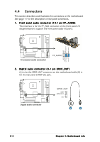
Digital audio connector (4-1 pin SPDIF_OUT)
Digital audio connector (4-1 pin SPDIF_OUT)
Digital audio connector (4-1 pin SPDIF_OUT)
Digital audio connector (4-1 pin SPDIF_OUT)
Digital audio connector (4-1 pin SPDIF_OUT)
(A) is for the SPDIF_OUT connector on the motherboard while (B) is
for the rear panel S/PDIF Out port.
A
B
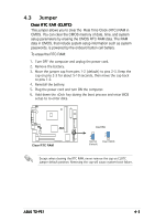
4.4
Connectors
This section describes and illustrates the connectors on the motherboard.
See page 1-7 for the description of rear panel connectors.
1.
1.
1.
1.
1.
Front panel audio connector (10-1 pin FP_AUDIO)
Front panel audio connector (10-1 pin FP_AUDIO)
Front panel audio connector (10-1 pin FP_AUDIO)
Front panel audio connector (10-1 pin FP_AUDIO)
Front panel audio connector (10-1 pin FP_AUDIO)
This interface is for the FP_AUD connector on the front panel I/O
daughterboard to support the front panel audio I/O ports.
/
Front panel audio connector
FP_AUDIO
BLINE_OUT_L
MIC2
Line out_R
Line out_L
BLINE_OUT_R
NC
MICPWR
+5VA
AGND
/
Digital audio connector
+5V
SPDIFOUT
GND
SPDIF_OUT