Asus T2-PE1 T2-PE1 English User Manual E2151 - Page 69

USB4_5, 7-pin USB6_7

Page 69 highlights

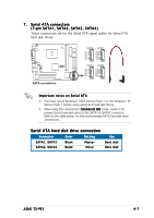
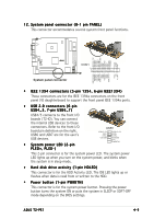
12. System panel connector (8-1 pin PANEL) This connector accommodates several system front panel functions. IEEE1394 +12V 1394 TPA1+ 1394 TPA11394 TPB1+ 1394 TPB1IEEE1394 GND USB6+ USB6USB GND USB7+ USB7USB GND PWRBTN# HDLED+5VSB GND ¤ CON1 1 IEEE1394 GND 1394 TPA0+ 1394 TPA01394 TPB0+ 1394 TPB0USB4_5 +5V USB4+ USB4USB GND USB5+ USB5USB7_8 +5V PLED+5V P_LED+ System panel connector • IEEE 1394 connectors (5-pin 1394, 6-pin IEEE1394) These connectors are for the IEEE 1394a connectors on the front panel I/O daughterboard to support the front panel IEEE 1394a ports. • USB 2.0 connectors (6-pin USB4_5, 7-pin USB6_7) USB4/5 connects to the front I/O boarde (T2-IO). You can connect the internal USB devices to these connectors. Refer to the front I/O board pin definition on the right. USB6 and USB7 are for the user's USB devices. • System power LED (2-pin PLED+, PLED-) USB1 USB4_5 +5V USB4USB4+ USB GND USB4_5 +5V USB5USB5+ USB GND +5V PWRBTN# This 2-pin connector is for the system power LED. The system power LED lights up when you turn on the system power, and blinks when the system is in sleep mode. • Hard disk drive activity (1-pin HDLED) This connector is for the HDD Activity LED. The IDE LED lights up or flashes when data is read from or written to the HDD. • Power button (1-pin PWRBTN) This connector is for the system power button. Pressing the power button turns the system ON or puts the system in SLEEP or SOFT-OFF mode depending on the BIOS settings. ASUS T2-PE1 4-9

  • 1
  • 2
  • 3
  • 4
  • 5
  • 6
  • 7
  • 8
  • 9
  • 10
  • 11
  • 12
  • 13
  • 14
  • 15
  • 16
  • 17
  • 18
  • 19
  • 20
  • 21
  • 22
  • 23
  • 24
  • 25
  • 26
  • 27
  • 28
  • 29
  • 30
  • 31
  • 32
  • 33
  • 34
  • 35
  • 36
  • 37
  • 38
  • 39
  • 40
  • 41
  • 42
  • 43
  • 44
  • 45
  • 46
  • 47
  • 48
  • 49
  • 50
  • 51
  • 52
  • 53
  • 54
  • 55
  • 56
  • 57
  • 58
  • 59
  • 60
  • 61
  • 62
  • 63
  • 64
  • 65
  • 66
  • 67
  • 68
  • 69
  • 70
  • 71
  • 72
  • 73
  • 74
  • 75
  • 76
  • 77
  • 78
  • 79
  • 80
  • 81
  • 82
  • 83
  • 84
  • 85
  • 86
  • 87
  • 88
  • 89
  • 90
  • 91
  • 92
  • 93
  • 94
  • 95
  • 96
  • 97
  • 98
  • 99
  • 100
  • 101
  • 102
  • 103
  • 104
  • 105
  • 106
  • 107
  • 108
  • 109
  • 110

4-9
4-9
4-9
4-9
4-9
ASUS T2-PE1
ASUS T2-PE1
ASUS T2-PE1
ASUS T2-PE1
ASUS T2-PE1
12.
12.
12.
12.
12. System panel connector (8-1 pin PANEL)
System panel connector (8-1 pin PANEL)
This connector accommodates several system front panel functions.
IEEE 1394 connectors (5-pin 1394, 6-pin IEEE1394)
These connectors are for the IEEE 1394a connectors on the front
panel I/O daughterboard to support the front panel IEEE 1394a ports.
USB 2.0 connectors (6-pin
USB4_5, 7-pin USB6_7)
USB4/5 connects to the front I/O
boarde (T2-IO). You can connect
the internal USB devices to these
connectors. Refer to the front I/O
board pin definition on the right.
USB6 and USB7 are for the user’s
USB devices.
System power LED (2-pin
PLED+, PLED-)
PLED+, PLED-)
PLED+, PLED-)
PLED+, PLED-)
PLED+, PLED-)
This 2-pin connector is for the system power LED. The system power
LED lights up when you turn on the system power, and blinks when
the system is in sleep mode.
Hard disk drive activity (1-pin HDLED)
This connector is for the HDD Activity LED. The IDE LED lights up or
flashes when data is read from or written to the HDD.
Power button (1-pin PWRBTN)
This connector is for the system power button. Pressing the power
button turns the system ON or puts the system in SLEEP or SOFT-OFF
mode depending on the BIOS settings.
/
System panel connector
1
CON1
IEEE1394 GND
1394 TPA0+
1394 TPA0-
1394 TPB0+
PLED-
+5V
P_LED+
USB5+
USB5-
USB7_8 +5V
USB4_5 +5V
USB4+
USB4-
USB GND
1394 TPB0-
IEEE1394 +12V
1394 TPA1+
1394 TPA1-
1394 TPB1+
HDLED-
+5VSB
GND
USB7+
USB7-
USB GND
IEEE1394 GND
USB6+
USB6-
USB GND
1394 TPB1-
PWRBTN#
USB1
USB4+
USB5+
USB GND
USB GND
+5V
PWRBTN#
USB4_5 +5V
USB4_5 +5V
USB4-
USB5-