Asus T2-PE1 T2-PE1 English User Manual E2151 - Page 36
optical drive. Connect the other
 |
View all Asus T2-PE1 manuals
Add to My Manuals
Save this manual to your list of manuals |
Page 36 highlights
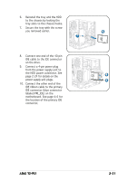
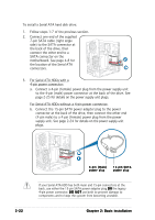
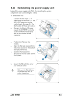
13. Reinstall the front panel cover by aligning its hooks with the chassis holes. 14. Lock the front panel cover hooks to the chassis holes as indicated. 13 14 To install a Serial ATA optical drive: 1. Follow steps 1 ~ 7 of the previous section "To install an IDE optical drive." 2. Connect one end of the Serial ATA cable to the Serial ATA interface at the back of the optical drive. Connect the other end to a Serial ATA connector 2 3 on the motherboard. See page 4-7 for the location of Serial ATA connectors. 3. Connect a Serial ATA power cable from the power supply unit to the Serial ATA power connector at the back of the drive. See page 2-24 for details on the power supply unit plugs. 2-18 Chapter 2: Basic installation
-
 1
1 -
2
-
3
-
4
-
5
-
6
-
7
-
8
-
9
-
10
-
11
-
12
-
13
-
14
-
15
-
16
-
17
-
18
-
19
-
20
-
21
-
22
-
23
-
24
-
25
-
26
-
27
-
28
-
29
-
30
-
 31
31 -
 32
32 -
 33
33 -
 34
34 -
 35
35 -
 36
36 -
 37
37 -
 38
38 -
 39
39 -
 40
40 -
 41
41 -
42
-
43
-
44
-
45
-
46
-
47
-
48
-
49
-
50
-
51
-
52
-
53
-
54
-
55
-
56
-
57
-
58
-
59
-
60
-
61
-
62
-
63
-
64
-
65
-
66
-
67
-
68
-
69
-
70
-
71
-
72
-
73
-
74
-
75
-
76
-
77
-
78
-
79
-
80
-
81
-
82
-
83
-
84
-
85
-
86
-
87
-
88
-
89
-
90
-
91
-
92
-
93
-
94
-
95
-
96
-
97
-
98
-
99
-
100
-
101
-
102
-
103
-
104
-
105
-
106
-
107
-
108
-
109
-
110
 |
 |

2-18
2-18
2-18
2-18
2-18
Chapter 2: Basic installation
Chapter 2: Basic installation
Chapter 2: Basic installation
Chapter 2: Basic installation
Chapter 2: Basic installation
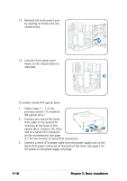
14.
Lock the front panel cover
hooks to the chassis holes as
indicated.
14
13.
Reinstall the front panel cover
by aligning its hooks with the
chassis holes.
13
To install a Serial ATA optical drive:
1.
Follow steps 1 ~ 7 of the
previous section “To install an
IDE optical drive.”
2.
Connect one end of the Serial
ATA cable to the Serial ATA
interface at the back of the
optical drive. Connect the other
end to a Serial ATA connector
on the motherboard. See page
4-7 for the location of Serial ATA connectors.
3.
Connect a Serial ATA power cable from the power supply unit to the
Serial ATA power connector at the back of the drive. See page 2-24
for details on the power supply unit plugs.
2
3