Asus TRL-DLS TRL-DLS User Manual - Page 15
ASUS TRL-DLS User's Manual, Jumper, Expansion Slots, Connectors - speakers
 |
View all Asus TRL-DLS manuals
Add to My Manuals
Save this manual to your list of manuals |
Page 15 highlights
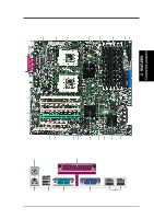
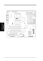
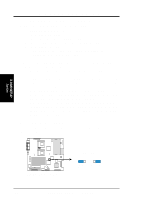
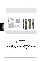
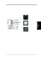
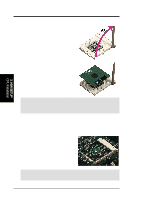
3. H/W SETUP Layout Contents 3. HARDWARE SETUP 3.2 Layout Contents Jumper 1) P1_66EN Expansion Slots 1) DIMMB1/2/3 DIMMA1/2/3 2) CPU 3) PCI66-1/2/3/4 PCI5, PCI6 Connectors 1) IDE1/IDE2 2 FLOPPY 3) WOL_CON 4) WOR 5) CHASSIS 6) CHA-WIDE, CHB-WIDE 7) CPUFAN1/2 SYSFAN1/2 8) SMB 9) eRMC 10) ATXPWR, CON12V 11) COM2 12) PCI66-4 13) USBPORT 14) PANEL - NIC - STATUS - PWRSW - RESET - PWR.LED - NMI - SPEAKER - IDELED p. 16 PCI Slot Setting p. 17 168-Pin System Memory Support p. 19 Central Processing Unit (CPU) p. 21 64-bit PCI Bus Expansion Slots p. 21 32-bit PCI Bus Expansion Slots p. 24 Primary/Secondary IDE Connectors (two 40-1 pin) p. 25 Floppy Disk Drive Connector (34-1 pin) p. 25 Wake-On-LAN Connector (3-pin) p. 26 Wake-On-Ring Connector (2-pin) p. 26 Chassis Open Alarm Lead (4-1 pin) p. 27 68-pin Ultra160 SCSI Connectors (two 68-pin) p. 28 CPU Fan Connectors (two 3-pin) p. 28 System Fan Connectors (two 3-pin) p. 29 SMBus Connector (6-1 pins) p. 29 ASUS Server Management Card Connector (50-pin) p. 30 ATX Power Supply Connector (20/24-pin) p. 30 12V Power Supply Connector (8-pin) p. 31 Serial Port 2 (10-1 pin) p. 31 Zero-channel RAID slot p. 32 Universal Serial Port Header (10-1pin male) p. 33 NIC Activity LED (2-pin) p. 33 Status Activity LED (2-pin) p. 33 ATX Power Switch/Soft Off Lead (2-pin) p. 33 Reset Switch Lead (2-pin) p. 33 System Power LED Lead (3-1 pin) p. 33 Non-Mask Interrupt Switch (2-pin) p. 33 System Warning Speaker Connector (4-pin) p. 33 IDE/SCSI Activity LED (2-pin) ASUS TRL-DLS User's Manual 15
-
 1
1 -
2
-
3
-
4
-
5
-
6
-
7
-
8
-
9
-
 10
10 -
 11
11 -
 12
12 -
 13
13 -
 14
14 -
 15
15 -
 16
16 -
 17
17 -
 18
18 -
 19
19 -
 20
20 -
21
-
22
-
23
-
24
-
25
-
26
-
27
-
28
-
29
-
30
-
31
-
32
-
33
-
34
-
35
-
36
-
37
-
38
-
39
-
40
-
41
-
42
-
43
-
44
-
45
-
46
-
47
-
48
-
49
-
50
-
51
-
52
-
53
-
54
-
55
-
56
-
57
-
58
-
59
-
60
-
61
-
62
-
63
-
64
-
65
-
66
-
67
-
68
-
69
-
70
-
71
-
72
-
73
-
74
-
75
-
76
-
77
-
78
-
79
-
80
-
81
-
82
-
83
-
84
-
85
-
86
 |
 |