Asus TRL-DLS TRL-DLS User Manual - Page 26
ASUS TRL-DLS User's Manual, Wake-On-Ring Connector 2-pin WOR, Chassis Intrusion Connector CHASSIS
 |
View all Asus TRL-DLS manuals
Add to My Manuals
Save this manual to your list of manuals |
Page 26 highlights
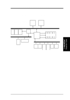
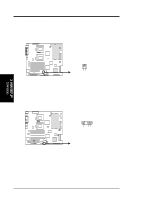
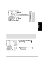
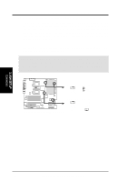
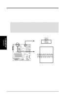
3. H/W SETUP Connectors 3. HARDWARE SETUP 4) Wake-On-Ring Connector (2-pin WOR) This connector connects to internal modem cards with a Wake-On-Ring output. The connector powers up the system when a ringup packet or signal is received through the internal modem card. NOTE: For external modems, Wake-On-Ring is detected through the COM port. ® TRL-DLS TRL-DLS Wake-On-Ring Connector WOR 1 2 Ground Ring# 5) Chassis Intrusion Connector (CHASSIS) This connector is designed for chassis intrusion detection. This requires an external detection mechanism such as a chassis intrusion sensor or microswitch. When any chassis component is removed, the sensor triggers and sends a highlevel signal to this connector to record a chassis intrusion event. ® TRL-DLS CHASSIS TRL-DLS Chassis Intrusion Lead +5Volt (Power Supply Stand By) Chassis Signal Ground 26 ASUS TRL-DLS User's Manual
-
 1
1 -
2
-
3
-
4
-
5
-
6
-
7
-
8
-
9
-
10
-
11
-
12
-
13
-
14
-
15
-
16
-
17
-
18
-
19
-
20
-
 21
21 -
 22
22 -
 23
23 -
 24
24 -
 25
25 -
 26
26 -
 27
27 -
 28
28 -
 29
29 -
 30
30 -
 31
31 -
32
-
33
-
34
-
35
-
36
-
37
-
38
-
39
-
40
-
41
-
42
-
43
-
44
-
45
-
46
-
47
-
48
-
49
-
50
-
51
-
52
-
53
-
54
-
55
-
56
-
57
-
58
-
59
-
60
-
61
-
62
-
63
-
64
-
65
-
66
-
67
-
68
-
69
-
70
-
71
-
72
-
73
-
74
-
75
-
76
-
77
-
78
-
79
-
80
-
81
-
82
-
83
-
84
-
85
-
86
 |
 |
