Asus TRL-DLS TRL-DLS User Manual - Page 32
ASUS TRL-DLS User's Manual, USB Header 10-1 pin USBPORT, System Panel Connector 20-pin PANEL
 |
View all Asus TRL-DLS manuals
Add to My Manuals
Save this manual to your list of manuals |
Page 32 highlights
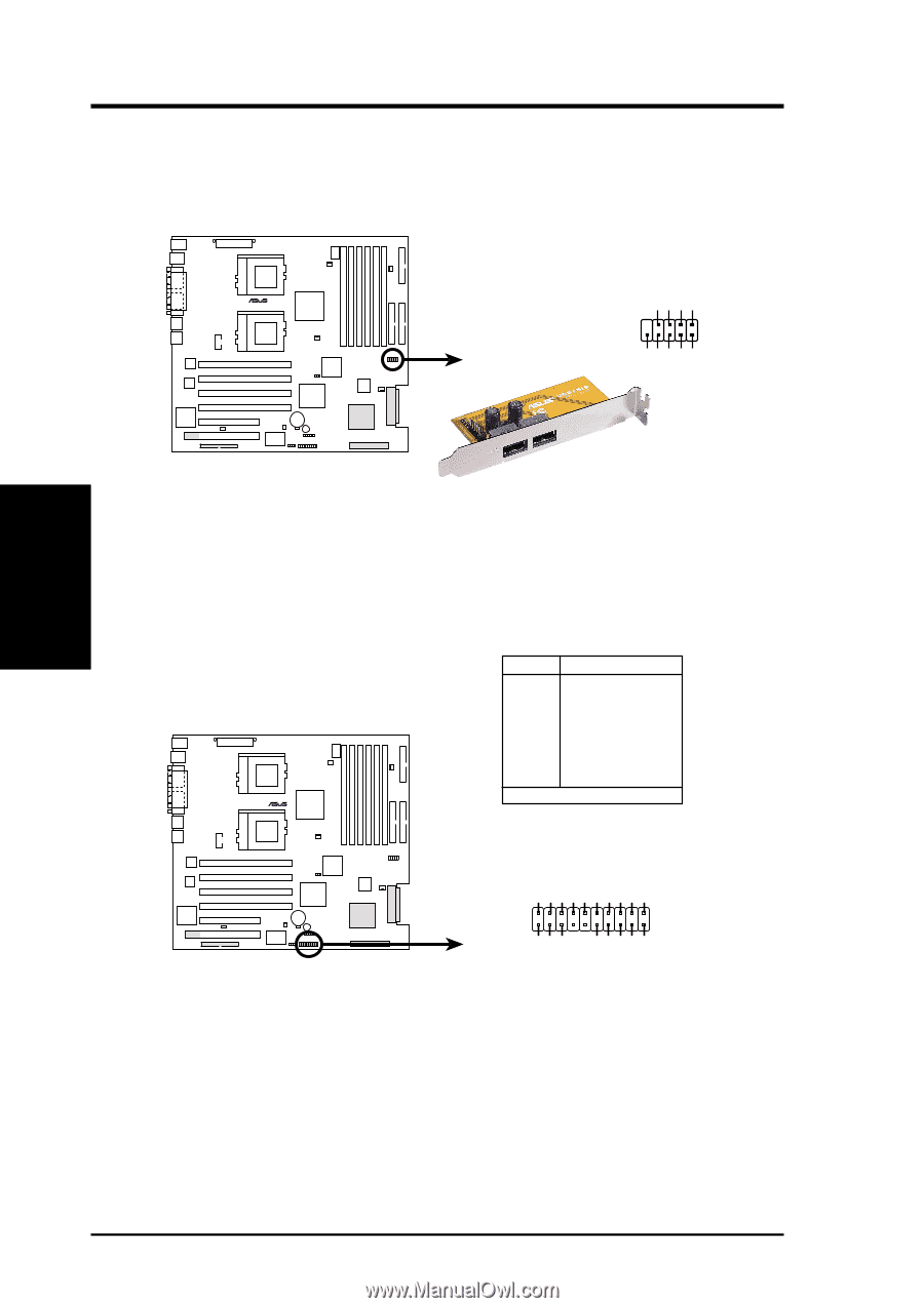
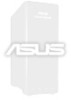
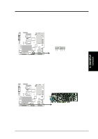
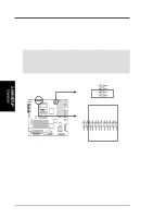
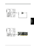
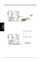
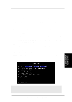
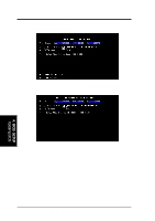
3. H/W SETUP Connectors 3. HARDWARE SETUP 13) USB Header (10-1 pin USBPORT) If the USB ports at the back panel are inadequate, one USB header is available for two additional USB port connectors. Connect the USB header to a 2-port USB connector set and mount the bracket to an open slot in the chassis. GND USBP3+ USBP3- USB Power ® TRL-DLS 10 6 USBPORT 5 1 NC GND USBP2+ USBP2- USB Power TRL-DLS USB Header 14) System Panel Connector (20-pin PANEL) This connector is for different front panel functions. See opposite page for the description of the connector leads. Pin Connector 1 & 12 2 & 3 6 & 7 9 & 10 11 & 13 14 15* & 16 17 & 20 18 & 19 NIC Activity LED Status LED Power Switch Reset Switch Power LED Keylock NMI Button Speaker HDD Access LED * Shared ® Power LED + NIC activity LED- Power LED - Keylock GND NMI button +5V HDD access LED+ HDD access LED- Speaker TRL-DLS 11 20 1 10 TRL-DLS System Panel Connectors NIC activity LED+ Status LED+ Status LED - Power Switch GND RESET button GND 32 ASUS TRL-DLS User's Manual
-
 1
1 -
2
-
3
-
4
-
5
-
6
-
7
-
8
-
9
-
10
-
11
-
12
-
13
-
14
-
15
-
16
-
17
-
18
-
19
-
20
-
21
-
22
-
23
-
24
-
25
-
26
-
 27
27 -
 28
28 -
 29
29 -
 30
30 -
 31
31 -
 32
32 -
 33
33 -
 34
34 -
 35
35 -
 36
36 -
 37
37 -
38
-
39
-
40
-
41
-
42
-
43
-
44
-
45
-
46
-
47
-
48
-
49
-
50
-
51
-
52
-
53
-
54
-
55
-
56
-
57
-
58
-
59
-
60
-
61
-
62
-
63
-
64
-
65
-
66
-
67
-
68
-
69
-
70
-
71
-
72
-
73
-
74
-
75
-
76
-
77
-
78
-
79
-
80
-
81
-
82
-
83
-
84
-
85
-
86
 |
 |