Asus TS300-E6 PS4 User Manual - Page 35
Installing ASUS PIKE RAID card
 |
View all Asus TS300-E6 PS4 manuals
Add to My Manuals
Save this manual to your list of manuals |
Page 35 highlights
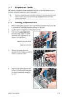
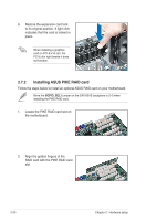
7. Connect the backplane cable to the two J4 connectors on the two 8 78 7 backplanes. 8. Connect two power supply cables to the two U1 connectors on the two backplanes. 9. Move the SGPIO_SEL1 jumper on the first SAS backplane to pin 2-3. 10. Connect the 8-1 pin end of the SGPIO cable to the SGPIO3 connector on the motherboard, and connect the 10-1 pin end of the SGPIO cable to the SGPIO3 connector on the first SAS backplane. Refer to section 2.8.1 Motherboard connections for the exact location of the SGPIO3 connector and section 2.8.2 SATA/SAS backplane connections for the exact locations of the SGPIO_SEL1 jumper, J4, U1 and SGPIO3 connectors. 8-1 pin cable end 10-1 pin cable end 11. Connect eight SAS cables to the SAS connectors on the two backplanes. 12. Connect the other ends of the SAS cables to the SAS connectors on the motherboard. Install a ASUS PIKE RAID card to the motherboard. Refer to section 2.7.2 Installing ASUS PIKE RAID card for details. ASUS TS300-E6/PS4 2-15
-
 1
1 -
2
-
3
-
4
-
5
-
6
-
7
-
8
-
9
-
10
-
11
-
12
-
13
-
14
-
15
-
16
-
17
-
18
-
19
-
20
-
21
-
22
-
23
-
24
-
25
-
26
-
27
-
28
-
29
-
 30
30 -
 31
31 -
 32
32 -
 33
33 -
 34
34 -
 35
35 -
 36
36 -
 37
37 -
 38
38 -
 39
39 -
 40
40 -
41
-
42
-
43
-
44
-
45
-
46
-
47
-
48
-
49
-
50
-
51
-
52
-
53
-
54
-
55
-
56
-
57
-
58
-
59
-
60
-
61
-
62
-
63
-
64
-
65
-
66
-
67
-
68
-
69
-
70
-
71
-
72
-
73
-
74
-
75
-
76
-
77
-
78
-
79
-
80
-
81
-
82
-
83
-
84
-
85
-
86
-
87
-
88
-
89
-
90
-
91
-
92
-
93
-
94
-
95
-
96
-
97
-
98
-
99
-
100
-
101
-
102
-
103
-
104
-
105
-
106
-
107
-
108
-
109
-
110
-
111
-
112
-
113
-
114
-
115
-
116
-
117
-
118
-
119
-
120
-
121
-
122
-
123
-
124
-
125
-
126
-
127
-
128
-
129
-
130
-
131
-
132
-
133
-
134
-
135
-
136
-
137
-
138
-
139
-
140
-
141
-
142
-
143
-
144
-
145
-
146
-
147
-
148
-
149
-
150
-
151
-
152
-
153
-
154
-
155
-
156
-
157
-
158
-
159
-
160
-
161
-
162
-
163
-
164
-
165
-
166
-
167
-
168
 |
 |
