Autodesk 05726-091452-9062 User Guide - Page 31
Saving Raster Images, Using AutoCAD Clipping Boundary when Selecting a Part of an, Image
 |
UPC - 606121590057
View all Autodesk 05726-091452-9062 manuals
Add to My Manuals
Save this manual to your list of manuals |
Page 31 highlights
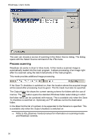
WiseImage- User's Guide To reload the unloaded image or to update the loaded image in order to ensure that you are working with the latest image file version, select it from the Image Manager dialog and click Reload. Þ If you close the drawing with images unloaded, then AutoCAD will not load these image files when you re-open this drawing, and you will have to load them manually. Saving Raster Images The rSave command saves a selected image to the current file. If an image is not linked to the file (a new image created during the current work session), then the program opens the raster image save dialog, where you must specify the raster file name, its location and format. If there is only one available image in the drawing (visible, located on unlocked layer), then it is automatically saved. Otherwise you should select a saved image either before or after invoking the command. If you did not selected an image before invoking the command, or if you selected several images, then a dialog box is displayed that contains a list of all inserted or selected images, and you should select the one to be saved. To save an image Select an image you want to save on the screen and: Click Save on the WiseImage toolbar. Choose Save from the rFile menu. Enter rSave command - or Use one of the above methods without selecting an image and select an image to save from the dialog box. Press OK. To save an image to another file use the WiseImage rSaveas command (or rFile > Save As). You can change an image file name, its location and format. This command saves the selected image to a new file and replaces the current image link path with the path to the newly created file. Therefore, after saving one of the image instances to a new file, all other instances to the saved image become linked to this file. The image logical name will not be changed. Using AutoCAD Clipping Boundary when Selecting a Part of an Image Using the clipping boundary, you can specify the part of an image to be displayed. The clipping boundary can be defined as a rectangle or a flat polygon with the vertices located within the image boundaries. Multiple instances of the same image can have different boundaries. Many WiseImage operation can be applied to clipping boundary. * A detailed description of the Image Clip command is provided in the AutoCAD User's Guide. 30
-
 1
1 -
2
-
3
-
4
-
5
-
6
-
7
-
8
-
9
-
10
-
11
-
12
-
13
-
14
-
15
-
16
-
17
-
18
-
19
-
20
-
21
-
22
-
23
-
24
-
25
-
 26
26 -
 27
27 -
 28
28 -
 29
29 -
 30
30 -
 31
31 -
 32
32 -
 33
33 -
 34
34 -
 35
35 -
 36
36 -
37
-
38
-
39
-
40
-
41
-
42
-
43
-
44
-
45
-
46
-
47
-
48
-
49
-
50
-
51
-
52
-
53
-
54
-
55
-
56
-
57
-
58
-
59
-
60
-
61
-
62
-
63
-
64
-
65
-
66
-
67
-
68
-
69
-
70
-
71
-
72
-
73
-
74
-
75
-
76
-
77
-
78
-
79
-
80
-
81
-
82
-
83
-
84
-
85
-
86
-
87
-
88
-
89
-
90
-
91
-
92
-
93
-
94
-
95
-
96
-
97
-
98
-
99
-
100
-
101
-
102
-
103
-
104
-
105
-
106
-
107
-
108
-
109
-
110
-
111
-
112
-
113
-
114
-
115
-
116
-
117
-
118
-
119
-
120
-
121
-
122
-
123
-
124
-
125
-
126
-
127
-
128
-
129
-
130
-
131
-
132
-
133
-
134
-
135
-
136
-
137
-
138
-
139
-
140
-
141
-
142
-
143
-
144
-
145
-
146
-
147
-
148
-
149
-
150
-
151
-
152
-
153
-
154
-
155
-
156
-
157
-
158
-
159
-
160
-
161
-
162
-
163
-
164
-
165
-
166
-
167
-
168
-
169
-
170
-
171
-
172
-
173
-
174
-
175
-
176
-
177
-
178
-
179
-
180
-
181
-
182
-
183
-
184
-
185
-
186
-
187
-
188
-
189
-
190
-
191
-
192
-
193
-
194
-
195
-
196
-
197
-
198
-
199
-
200
-
201
-
202
-
203
-
204
-
205
-
206
-
207
-
208
-
209
-
210
-
211
-
212
-
213
-
214
-
215
-
216
-
217
-
218
-
219
-
220
-
221
-
222
-
223
-
224
-
225
-
226
-
227
-
228
-
229
-
230
-
231
-
232
-
233
-
234
-
235
 |
 |
