Behringer K-2 Quick Start Guide - Page 9
Step 2: Controls - manual
 |
View all Behringer K-2 manuals
Add to My Manuals
Save this manual to your list of manuals |
Page 9 highlights
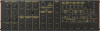
16 K-2 K-2 Controls (EN) Step 2: Controls Voltage Controlled Oscillators Section (1) WAVEFORM - select the VCO 1 waveform from: triangular, reverse sawtooth, pulse, or noise. (2) PW - adjust the VCO 1 pulse width (when in pulse mode) from square to narrow. (3) SCALE - select the VCO 1 octave from 32', 16', 8', or 4'. (4) WAVEFORM - select the VCO 2 waveform from: reverse sawtooth, square, narrow pulse, or RING (with VCO1). (5) PITCH- adjust the VCO 2 pitch. (6) SCALE- Select the VCO 2 octave from 16', 8', 4', or 2'. Controllers Section (7) PORTAMENTO - adjust the amount of Portamento (Glide time), between notes on the keyboard. (8) MASTER TUNE - adjust the overall tuning of the synthesizer to match other instruments. VCO Mixer Section (9) VCO1 LEVEL - adjust the VCO 1 amplitude level. (10) VCO 2 LEVEL - adjust the VCO 2 amplitude level. Frequency Modulation Section (11) MG/T.EXT - adjust the amount of frequency modulation by the modulation generator (MG) or T.EXT (if a connection is made to the TOTAL input). (12) EG1/EXT - adjust the amount of frequency modulation by envelope generator 1 (EG1) or EXT (if a connection is made to the FREQ input). Voltage Controlled Filter Section (13) CUTOFF FREQUENCY - adjust the cutoff frequency of the high-pass filter. Frequencies below the cutoff will be attenuated. (14) PEAK - select the amount of emphasis in level at the cutoff frequency. (15) CUTOFF FREQUENCY - adjust the cutoff frequency of the low-pass filter. Frequencies above the cutoff will be attenuated. (16) PEAK - select the amount of emphasis in level at the cutoff frequency. (17) FILTER 1/2 - select between filter type 1 or 2. Cutoff Frequency Modulation Section (18) MG/T.EXT - adjust the amount of cutoff frequency modulation of the high-pass filter by the modulation generator (MG) or T.EXT (if a connection is made to the TOTAL input). (19) EG2/EXT - adjust the amount of cutoff frequency modulation of the high-pass filter by the envelope generator 2 (EG2) or EXT (if a connection is made to the high pass filter CUTOFF FREQ input). (20) MG/T.EXT - adjust the amount of cutoff frequency modulation of the low-pass filter by the modulation generator (MG) or T.EXT (if a connection is made to the TOTAL input). (21) EG2/EXT - adjust the amount of cutoff frequency modulation of the low-pass filter by envelope 2 (EG2) or EXT (if a connection is made to the low-pass filter CUTOFF FREQ input). MIDI IN Section (22) MIDI IN - this 5-pin DIN jack receives MIDI data from an external source. This will commonly be a MIDI keyboard, an external hardware sequencer, a computer equipped with a MIDI interface, etc. Modulation Generator Section (23) LED - indicates the current rate of the modulation generator. (24) WAVEFORM - adjust the waveform of the modulation generator from reverse sawtooth, through triangle, to sawtooth. It also affects the second available waveform from wide, square, to narrow. (25) FREQUENCY - adjust the frequency of the modulation generator from 0.1 to 22 Hz. The generator is also known as a low frequency oscillator (LFO). Envelope Generator Section Envelope 1 affects the frequency modulation. Envelope 2 affects the cutoff frequency modulation, as well as the amplitude modulation of the voltage controlled amplifier (VCA). (26) DELAY TIME - controls the time between the arrival of the trigger signal and the start of the attack time. (27) ATTACK TIME - controls the time it takes for envelope 1 to reach a maximum level after a note is played. (28) RELEASE TIME - controls the release time of envelope 1 after the note is released. (29) HOLD TIME - controls the amount of time that the trigger signal is held (extended). (30) ATTACK TIME - controls the attack time of envelope 2. Quick Start Guide 17 (31) DECAY TIME - controls the decay time of envelope 2 after the attack time is over. (32) SUSTAIN LEVEL- controls the level of envelope 2 that is sustained after the attack time and initial decay time have been reached. (33) RELEASE TIME - controls the release time of envelope 2 after the note is released. General Section (34) POWER LED - this indicates when power is supplied to the unit, and the rear panel power switch is on. (35) VOLUME - adjust the overall volume level of the synthesizer output. (36) SIGNAL OUT - use this 3.5 mm TS connection to output the main line-level audio signals. (37) PHONES - connect your headphones to this 3.5 mm TRS output. Make sure the volume is turned down before putting on headphones. Patchbay (3.5 mm TS connections) Main Signal Path (38) TOTAL - modulation input for VCO 1, VCO 2, high-pass, and low-pass VCF. (39) FREQ - modulation input for VCO 1 and VCO 2. (40) EXT SIGNAL IN - external audio signal input. (41) CUTOFF FREQ - high-pass cutoff frequency modulation input. (42) CUTOFF FREQ - low-pass cutoff frequency modulation input. (43) INITIAL GAIN - VCA modulation input. Modulation and Envelopes (44) MG OUT- modulation generator output (reverse sawtooth/triangle/sawtooth). (45) MG OUT - modulation generator output (wide pulse/square/narrow). (46) EG 1 OUT - envelope generator 1 output. (47) EG 1 REV OUT - envelope generator 1 output-reversed. (48) EG1 TRIG IN - envelope 1 trigger input. (49) EG 2 REV OUT - envelope generator 2 output-reversed. (50) VCO 2 CV IN - VCO 2 CV input. (51) VCO 1+2 CV IN - VCO 1 and VCO 2 CV input. (52) KBD CV OUT - keyboard CV output. (53) TRIG OUT - trigger output. (54) TRIG IN - trigger input. Sample and Hold (55) S&H IN - sample and hold input. (56) CLOCK - sample and hold clock input. (57) S&H OUT - sample and hold output. VCA (58) VCA IN - VCA input. (59) VCA CONTROL INPUT - VCA control input. (60) VCA OUT - VCA control output. Noise Generator (61) PINK - output from the pink noise generator. (62) WHITE - output from the white noise generator. (63) TRIG SW OUT - trigger switch output. (64) TRIG SW- manual trigger switch. External Signal Processor Section (65) SIGNAL IN - external signal input. (66) OUT - external signal output, pre-filter. (67) OUT - external signal output, post-filter. (68) F - V CV OUT - CV output after frequency to voltage conversion. (69) PEAK - LED indicates peak signal. (70) ENV OUT - envelope output. (71) LED - indicates trigger output (72) TRIG OUT - trigger output. (73) SIGNAL LEVEL - adjusts the external input signal level. (74) LOW CUT FREQ - adjusts lower frequency of band-pass filter. (75) HIGH CUT FREQ- adjusts upper frequency of band-pass filter. (76) CV ADJUST - adjusts level of CV control voltage. (77) THRESHOLD LEVEL - adjusts the threshold level.
-
 1
1 -
2
-
3
-
 4
4 -
 5
5 -
 6
6 -
 7
7 -
 8
8 -
 9
9 -
 10
10 -
 11
11 -
 12
12 -
 13
13 -
 14
14 -
15
-
16
-
17
-
18
-
19
-
20
-
21
-
22
-
23
-
24
-
25
 |
 |
