Behringer MODEL D Quick Start Guide - Page 23
MODEL D Eurorack Installation
 |
View all Behringer MODEL D manuals
Add to My Manuals
Save this manual to your list of manuals |
Page 23 highlights
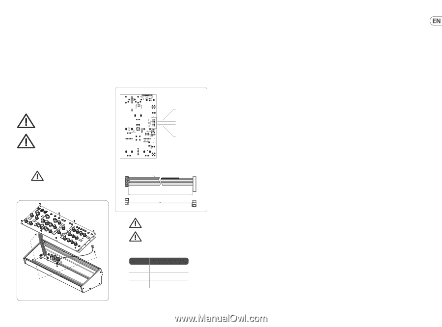
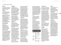
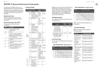
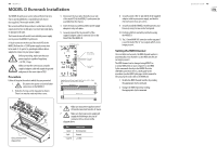
44 MODEL D MODEL D Eurorack Installation The MODEL D synthesizer can be removed from its factory chassis and installed into a standard Eurorack chassis (not supplied). The module width is 70HP. We recommend that this procedure is undertaken only by experienced service technicians, to prevent personal injury, or damage to the unit. The Eurorack case will need its own suitable power supply unit to power the MODEL D synthesizer. A 10-pin connector on the rear of the main PCB of the MODEL D allows the +12 VDC power supply connection to be made. A 10-pin to 16-pin adapter ribbon cable is supplied to connect to your power supply. Before proceeding, make sure that your power supply is capable of supplying +12 VDC, 1 Amp. Make sure that the connections using the supplied adapter cable will supply the ground and power to the correct pins of X23. Procedure Follow all steps in the order in which they are presented. 1. Disconnect the power cord and all other connections to the MODEL D. 2. Undo the 8 screws on the top panel as shown. There is no need to undo any other screws. 3. Disconnect the two cables from the lower side of the main PCB of the MODEL D, and remove the assembly from the chassis. 4. Store the chassis assembly and the power supply adaptor in a dry safe place. 5. Securely connect the 10-pin end P1 of the supplied adapter cable to connector X23 on the Main PCB of the MODEL D. X21 No Connection Pins 1 and 2 No Connection X23 Pins 3 to 8 Ground Pins 9 and 10 +12 VDC Supplied Eurorack Power Supply Cable, Part # A74-0001-79446 Connect End P1 to Connector X23 on main PCB P1 21 Red Stripe P2 12 10 9 400 mm ± 10 15 16 Disconnect from Main PCB 6. Make sure your power supply is turned off and disconnected from the AC mains. 7. Make sure that your power supply will supply the following to the pins of connector X23, as shown in the diagram above: Pins 1 and 2 3 to 8 9 and 10 Connection No Connection Ground +12 VDC 8. Securely connect the 16-pin end P2 of the supplied adapter cable to your power supply, and double check all connections are correct. 9. Securely install the MODEL D Synthesizer into your Eurorack, using 8 screws in the front panel. 10. Perform a full test and safety test before using the MODEL D. 11. The 3.5 mm MAIN OUT connector on the top panel is used instead of the ¼" rear outputs which are no longer present. Setting the MIDI Channel Once installed in a Eurorack, the MIDI channel number is automatically set to channel 1 (as the MIDI switches are no longer present.) The MIDI channel can be changed using MIDI OX or a similar MIDI utility on your computer to send MIDI SysEx commands directly to the MODEL D via the USB MIDI connection. Here is a brief guide to the procedure (see the MIDI SysEx pages in this manual for the actual SysEx codes sent to the MODEL D): 1. Disable the MIDI Channel Switches by sending the appropriate SysEx command. 2. Change the MIDI Channel by sending the appropriate SysEx command. Quick Start Guide 45
-
 1
1 -
2
-
3
-
4
-
5
-
6
-
7
-
8
-
9
-
10
-
11
-
12
-
13
-
14
-
15
-
16
-
17
-
 18
18 -
 19
19 -
 20
20 -
 21
21 -
 22
22 -
 23
23 -
 24
24 -
 25
25 -
 26
26 -
 27
27 -
 28
28
 |
 |