Behringer MODEL D Quick Start Guide - Page 9
Step 2: Controls - manual
 |
View all Behringer MODEL D manuals
Add to My Manuals
Save this manual to your list of manuals |
Page 9 highlights
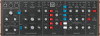
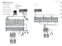
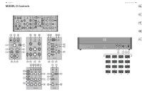
16 MODEL D MODEL D Controls (EN) Step 2: Controls MIDI Section (1) USB PORT - This USB type B jack allows connection to a computer. The MODEL D will show up as a class-compliant USB MIDI device, capable of supporting MIDI in and out. USB MIDI IN - accepts incoming MIDI data from an application. USB MIDI OUT - sends MIDI data to an application. (2) MIDI IN - this 5-pin DIN jack receives MIDI data from an external source. This will commonly be a MIDI keyboard, an external hardware sequencer, a computer equipped with a MIDI interface, etc. (3) MIDI THRU - this 5-pin DIN jack is used to pass through MIDI data received at the MIDI INPUT. This will commonly be sent to another MODEL D synthesizer to run a Poly Chain or to a drum machine assigned to a different MIDI Channel. Controllers Section (4) OSC3/FILTER EG - switch between OSC 3 or the Filter Envelope as a modulation source. (5) GLIDE - adjust the amount of Glide (Portamento), between notes on the keyboard. (6) TUNE - adjust the frequency of oscillators 1, 2, and 3. (OSC3 is not affected if the OSC3 CONTROL switch is off.) (7) OSCILLATOR MODULATION when ON, the three oscillators are modulated by the modulation mix, set by the MOD MIX knob. (8) MOD MIX - adjust the modulation mix between OSC3/Filter EG and Noise/LFO. (9) NOISE (MOD SRC)/ LFO - switch between Noise (or external modulation source) or Low Frequency Oscillator (LFO) as a modulation source. (10) MOD DEPTH - adjust the modulation depth from off to maximum. The modulation depth can also be adjusted using the modulation wheel on a MIDI keyboard. (11) WAVE SHAPE - select the LFO wave shape from either triangular or square wave. (12) LFO RATE - adjusts the frequency of the LFO. Oscillator Bank Section (13) OSC 3 CONTROL - when ON, the frequency of Oscillator 3 will vary with the keyboard. When OFF, the keyboard, Pitch wheel, and Modulation wheel, will have no effect on OSC3. (14) FREQUENCY RANGE - select from six frequency ranges of Oscillator 1, 2, or 3. (15) FREQUENCY ADJUSTMENT adjust the frequency of Oscillator 2 or 3. (16) WAVE SHAPE - select the wave shape used for Oscillator 1, 2, or 3 from: triangular, triangular/ sawtooth (OSC 1 and 2), reverse sawtooth (OSC 3), sawtooth, square, medium pulse, and narrow pulse. (17) MOD SOURCE (INPUT) - allows connection of an external modulation source. If nothing is connected here, then the internal Noise generator is available as a modulation source. (18) OSC 1V/OCT (INPUT) - this input allows the frequency of the three oscillators to be adjusted by an external control voltage (1 Volt input increase, will increase the frequency by one Octave). (19) LFO CV (INPUT) - allows control of the LFO frequency by an external control voltage. Mixer Section (20) VOLUME - adjust the volume of Oscillator 1, 2, or 3. (21) ON/OFF - select the sources to play from OSC 1, OSC 2, OSC 3, Noise, and External Input, or any combination of these 5 sources. (22) NOISE VOLUME - adjust the level of the internal Noise source. (23) WHITE/PINK - switch the internal Noise source from Pink noise to White noise. (24) OVERLOAD - indicates when the audio levels of the mix are overloading the mixer section. (25) EXT IN VOLUME - adjust the level of any external source playing into the external Input. If nothing is connected to the external input, then instead of any external audio coming in at this point, the main MODEL D output is automatically connected here. This creates a feedback path from the output back into the mixer section, to get extra phat bass or extra crunch. In this case, the EXT IN volume control will adjust the level of the incoming main audio fed back into the mixer section. (26) LFO Triangular (OUTPUT) - outputs the internal LFO triangular-wave signal. (27) LFO Square (OUTPUT) outputs the internal LFO square-wave signal. (28) EXT (INPUT) - connect any external line-level audio source to this 3.5 mm input. If nothing is connected here, then the main audio output is internally connected to this external input. (29) MIX (OUTPUT) - outputs the final mix from this Mixer section. Modifiers Section (30) DECAY - when ON, the signal will decay during the time set by the DECAY TIME knob after a note or external trigger is released. When OFF, it will decay immediately after a note or external trigger is released. LOUDNESS DECAY - affects the decay of volume level of the Loudness section. FILTER DECAY - affects the decay of the cutoff frequency of the Filter section. (31) KEYBOARD CONTROL - these switches vary the effect of the keyboard tracking, where the filter section is affected by the pitch of note played. Switch 1 and 2 OFF - no keyboard tracking effect Switch 1 and 2 ON maximum effect Switch 1 ON (only) - 1⁄3 of maximum effect Switch 2 ON (only) - 2⁄3 of maximum effect Quick Start Guide 17 (32) FILTER MODULATION - when ON, attenuated. In high-pass mode, (48) LOUD CV (INPUT) - allows the filter section is modulated by audio frequencies below the cutoff connection of an external the modulation mix, set by the frequency are attenuated. control voltage to control the MOD MIX knob. CUTOFF FREQUENCY - adjusts the Loudness Contour. (33) FILTER MODE - select the filter cut-off frequency of the filter. (49) MAIN (OUTPUT) - use this 3.5 between Low-pass or High-pass. FILTER EMPHASIS - adjusts (34) LOUDNESS CONTOUR - these 3 the amount of volume level knobs adjust the overall shape boost (resonance) given at the enveloping the audio after it has cut-off frequency. passed through the mixer section and filter section. The controls affect the change in volume (loudness) level with time. AMOUNT OF CONTOUR - adjusts the amount of frequency shift given to the cutoff frequency. ATTACK - adjust the time it takes for the signal to reach a maximum level after a note is played. (37) CUT CV (INPUT) - allows connection of a control voltage to control the cutoff frequency. DECAY TIME - adjust the time for a signal to decay down to the sustain volume level after the attack time is over. If the LOUDNESS DECAY (38) FC GATE (INPUT) - allows an external trigger voltage to be applied to trigger the filter contour. switch is ON, this is also how long (39) FILT CONT (OUTPUT) - outputs mm TRS connection to output the main audio output. Typically it is patched to an audio input of the MODEL D or the audio inputs of other modular synthesizer equipment. If you are using the MODEL D in a Eurorack, then this is the main output, as the rear panel output connectors are not used. Rear Panel (50) MAIN OUTPUT - connect these ¼" TRS outputs to the inputs of your external equipment as follows (note that they are both Mono, and not left/right): LOW - this instrument-level it takes to decay to minimum once the filter contour. mono output can connect to the a note is released. (40) LC GATE (INPUT) - allows SUSTAIN - adjust the volume level an external trigger voltage that the signal is sustained after to be applied to trigger the the attack time and initial decay loudness contour. instrument-level inputs of guitar amplifiers or mixers for example. HIGH - this line-level mono output can connect to the line-level time have been reached. (35) FILTER ENVELOPE CONTROLS these 3 knobs adjust the overall shape enveloping the filter section. The controls affect the change in cutoff frequency with time. ATTACK - adjust the time for the cutoff frequency to increase from its set value and reach the frequency set by the AMOUNT OF CONTOUR control. DECAY TIME - adjust the time for the cutoff frequency to decay down to the sustain frequency after the attack time is over. If the FILTER DECAY switch is ON, then this decay time is also how long it takes to decay from the sustain (41) LOUD CONTOUR (OUTPUT) outputs the loudness contour. Output Section (42) A-440 - use this to turn on an output tuning signal of 440 Hz concert pitch. This switch can also be used to enter various modes during turn-on (see the Getting Started section of this manual for more details). (43) POWER - this LED shows when power is applied and the synthesizer is turned on. (44) VOLUME - adjust the overall volume level of the synthesizer output. (45) VOLUME (HEADPHONE) - adjust the overall volume level of the inputs of mixers, keyboard amplifiers, or powered speakers for example. (51) MIDI CHANNEL - these 4 switches allow you to set the MIDI Channel number from 1 to 16 (see the table on page 15). The MIDI channel can also be changed using MIDI SysEx commands, as shown in the MIDI SysEx tables later in this manual. (This method is used when the MODEL D is housed in a Eurorack, and these switches are no longer present.) (52) POWER - turn the synthesizer on or off. Make sure all the connections are made before turning on the unit. (53) DC INPUT - connect the supplied frequency once a note is released. PHONES output. 12V DC power adapter here. SUSTAIN - adjust the cutoff to a (46) PHONES - connect your frequency which is sustained after headphones to this 3.5 mm the attack time and initial decay TRS output. Make sure the time have been reached. headphone volume is turned down (36) FILTER CONTROLS - the filter before putting on headphones. The power adapter can be plugged into an AC outlet capable of supplying from 100V to 240V at 50 Hz/60 Hz. Use only the power adapter supplied. can be low-pass or high-pass, (47) ON - use this to quickly turn on depending on the setting of the or Mute the main audio output of FILTER MODE switch. In low- the synthesizer. pass mode, audio frequencies above the cutoff frequency are
-
 1
1 -
2
-
3
-
 4
4 -
 5
5 -
 6
6 -
 7
7 -
 8
8 -
 9
9 -
 10
10 -
 11
11 -
 12
12 -
 13
13 -
 14
14 -
15
-
16
-
17
-
18
-
19
-
20
-
21
-
22
-
23
-
24
-
25
-
26
-
27
-
28
 |
 |