Behringer WING Quick Start Guide 1 - Page 6
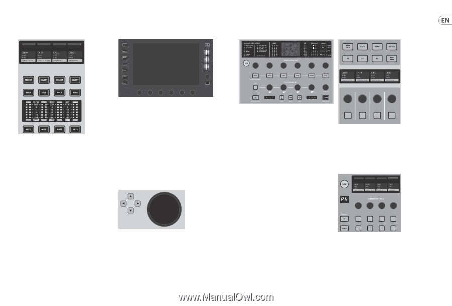
Scribble strips, meters, select, Main Display, Channel Strip Channel Custom - daw control
 |
View all Behringer WING manuals
Add to My Manuals
Save this manual to your list of manuals |
Page 6 highlights
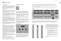
10 WING WING Overview Scribble strips, meters, select Main Display Channel Strip Section 4-Channel Section Quick Start Guide 11 Each fader strip has a mini display screen called a scribble strip. This will indicate information about the current channel/bus number, name and even a graphic icon to quickly identify which channel is currently controlled by the fader and associated buttons. A color bar above the scribble strip allows quick visual identification of groups of related channels. Scribble strip details and color bar options can be edited on the HOME screen/HOME tab by pressing the CUSTOMIZE button. Pressing the SELECT button directs the control focus of the Main Display and Channel Strip section to that channel or bus. Only one SELECT button can be active at any time. The SOLO button will isolate that channel for monitoring, along with any other channels or buses that are soloed. The MUTE button mutes the channel currently assigned to that strip. Stereo level meters provide input level information at a glance, from -60 dB to Clip. The DYNAMICS LED will light whenever the dynamics threshold is exceeded, thus triggering the compressor/expander. Likewise, the GATE LED will light whenever the input signal falls below the noise gate threshold. The majority of the WING's controls can be edited and monitored via the 10" touch screen Main Display. Various screens can be accessed with the 7 buttons along the left side of the screen, as well as the VIEW buttons located in each major section of the top panel. 6 encoders along the bottom of the display allow parameter adjustments of the items shown at the bottom of the current display screen. These are capacitive knobs that will highlight elements on the screen as soon as the associated knob is touched. An additional 7th encoder to the right of the display can be used for contextdependent control by first touching an item on the Main Display, allowing for finer adjustments compared to moving virtual knobs or faders. A multi-purpose button beneath the 7th encoder performs similarly depending on the current screen. For example, it can be used as a tap tempo when editing delay effects. The large stereo meter will either display the main bus or solo bus levels. The CLR SOLO button will release all channels and buses that are active in the solo bus. An overview of each screen is presented in Chapter 3. The navigation arrows and value/scrub wheel perform functions pertaining to DAW control as well as the USB Audio and WING-LIVE players. The wheel can also fine-tune values of parameters assigned in the User layer of the Custom Controls while respective buttons are depressed. The channel strip provides quick access to the primary parameters for the currently-selected channel. A display screen provides dedicated editing details for the parameter being adjusted, and various indications for input configuration, bus and group assignments, and metering are always visible for convenience. One of 7 channel editing blocks (including EQ) can be sent to the editing display screen by pressing the associated button or touching the capacitive encoder knob directly above. Press and hold the button to turn the block on or off. Pressing the VIEW button will open the HOME screen of the selected channel on the Main Display. Once a block is already active, pressing the block button again will scroll through several parameters for editing, and the associated encoder can be used for adjustments. Small dots in the lower right corner of the display indicate how many parameters can be scrolled through by repeatedly pressing the block button. An additional EQ section has dedicated controls for adjustment of up to 6 EQ bands for input channels and 8 bands for buses. Engage the EQ block by pressing and holding the EQ button, then touch one of the 4 EQ encoder knobs to select a band for adjustment. Press the SHIFT button to access the low and hi shelf bands, and additional bands if editing a bus EQ. The edit section above the righthand fader bank offers a special set of dedicated control elements. This can be parameters like gain, pan, filters or effects sends for the selected bank of 4 channels. Pressing one of the 8 buttons enables the 4 knobs and 4 buttons to control channel properties without actually selecting the channel for editing. This makes the 4-channel section independent from the main control surface, and would allow for a second audio engineer to work in parallel to the FOH engineer. Custom Controls The GAIN, WIDTH and FREQ buttons select which element of the current band will be adjusted with the encoder. Press the LISTEN button in the lower right corner to monitor the EQ band in isolation. The BLEND/MIX knob acts as a wet/dry adjustment for the EQ block. This can be used to exaggerate or de-emphasize the current EQ setting. The Custom Controls section allows up to 4 rotary knobs and 8 buttons to be configured for control of specific elements that should be available at all times regardless of the main display screen focus. A common use could be the vocal channel's reverb send level. Presets can also be configured to suit different sets, venues, operators, etc. Press the VIEW button to assign functions to the controls, optimize the scribble strips, or reset the controls.
-
 1
1 -
 2
2 -
 3
3 -
 4
4 -
 5
5 -
 6
6 -
 7
7 -
 8
8 -
 9
9 -
 10
10 -
 11
11 -
 12
12 -
13
-
14
-
15
-
16
-
17
-
18
-
19
-
20
-
21
-
22
-
23
-
24
-
25
-
26
-
27
-
28
-
29
-
30
-
31
-
32
-
33
-
34
-
35
 |
 |