Behringer WING Quick Start Guide 1 - Page 8
Patching and Setup, Presets and Snapshots Library, Firmware Updates - manual
 |
View all Behringer WING manuals
Add to My Manuals
Save this manual to your list of manuals |
Page 8 highlights
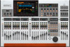
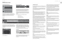
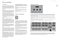
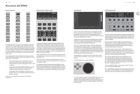
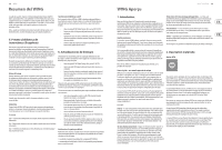
14 WING WING Overview Additional VIEW-based screens: INPUT/BUS/MAIN - Pressing the VIEW button in any of the 3 fader sections will bring up an overview screen to monitor all input, bus or output channels at once. MONITOR - Even though the top panel Monitor section has some hardware controls, a significant amount of configuration is available via the VIEW button to determine where Talkback paths are heard, monitor A and B sources, monitor bus EQ and metering, dimming levels, and more. CHANNEL STRIP - The VIEW button in the Channel Strip will call up a screen relevant to the block that is currently being edited. All of the screens that are accessed with the Channel Strip VIEW button are also accessible via the Main Display HOME button, but provide more immediate access. CUSTOM CONTROLS - The top and bottom portions of the Custom Control section each have their own VIEW button to edit the functions that are controlled by the hardware elements. 4. Patching and Setup To help understand the basics of patching and signal flow, here is an example scenario that might be common for a live music event. In this hookup, the audio sources on stage are connected to an S16 stage box which sends the signals via shielded ethernet cable to the WING's AES50-A port. The physical connections to the stage box are a bit disorganized, but this can be repatched in the console in a more standardized way. S16 Input Physical Connection 1 Bass guitar DI 2 Lead guitar 3 Keyboard L 4 Keyboard L 5 Backing track L 6 Backing track R 7 Vocal stage R 8 Kick drum 9 Tom 1 10 Tom 2 11 Tom 3 12 Snare 13 Overhead 1 14 Overhead 2 15 Vocal stage L 16 Acoustic DI Source AES-A 1 AES-A 2 AES-A 3/L (linked) AES-A 4/R AES-A 5/L (linked) AES-A 6/R AES-A 7 AES-A 8 AES-A 9 AES-A 10 AES-A 11 AES-A 12 AES-A 13/L (linked) AES-A 14/R AES-A 15 AES-A 16 Channel Assignment 7 8 10 (stereo) 10 (automatic) 11 (stereo) 11 (automatic) 12 1 2 3 4 5 6 (stereo) 6 (automatic) 13 9 The Source is what gives meaning and identity to an input, which makes patching WING Sources to channels very evident and clear. Press the ROUTING button and touch the pull-down menu at the top of the screen. Select 'AES50 A' from the list of input groups. Press the 'A 1' square, which will allow the Source details to be defined, including the name, icon, color, phantom power, and even preliminary gain adjustment. If a pair of Sources should be linked as stereo or mid-side, this can be done as well. Note that the odd-numbered Source will always occupy the left side, and the even-numbered Source direct above it will occupy the right. Be sure to arrange your physical connections accordingly. Press the HOME button on the Main Display and then the SELECT button for channel 1 in the first fader bank. If no Source is selected, no gain adjustment can be made. Press 'INPUT' on the HOME screen, or navigate to the second tab in the left-hand column. Press the Source Select square under the MAIN section and select AES50 A from the pull-down menu. Tap'A 8'in the grid to assign the kick drum to channel 1. Without leaving this page, press the SELECT button for channel 2 in the first fader bank. Select AES50 A-9 to assign Tom 1 to channel 2. Continue through the other channels to assign the otherwise messy physical connections at the stage box in a logical and organized manner. When assigning the overhead mics to channel 6, pressing AES 13/L will automatically route both mic signals to channel 6 in stereo. On the ROUTING screen, press the output icon at the top of the screen. Touch the Output Group pull-down menu and select 'AES50 A'. Press the first square in the grid. Touch the Input Group pull-down menu and select BUS. Select 1L to assign bus 1 to XLR output 1 on the S16. Repeat this process for any other bus sends back to the stage. When editing output 7 and 8, select MAIN from the Input Group menu, then assign 1L to output 7 and 1R to output 8. These outputs will be connected to your power amplifiers or active main speakers. Note - when using mono stage wedges, use the Mono button in the input section to set width to 0. Quick Start Guide 15 5. Presets and Snapshots Library 6. Firmware Updates After putting in the effort to adjust the routing, channel processing and global preferences, it is highly recommended that a Snapshot be created to preserve the console state. This can be done in the Library section. Many options exist to select both the way that these are saved, as well as how the console state is protected when loading previously-saved Snapshots. The left-hand pane of the Snapshot Library will show a list of your Snapshots that have been saved to the main directory, as well as any folders that you have created to organize similar Snapshots. If many Snapshots are likely to be saved, or if multiple engineers will be using the console, then it may be more efficient to make good use of folders. Recall Scope Various elements of the console, including routing, channel processing, and global configuration can be selected or omitted both when saving and recalling a saved Snapshot. Channels, buses and FX engines will expand for easier select/deselect. Adjusting the recall scope prior to saving can act as a reminder to the purpose for that Snapshot being saved in the first place. When a saved Snapshot is selected from the library list, the state of the recall scope at the time the Snapshot was saved will be displayed. This also allows the scope to be further adjusted before loading. When the Snapshot is loaded, only the elements highlighted in blue will be affected. Global Safes Touch the GLOBAL SAFES button at the top of the screen to access these options. Certain elements can be protected from ever being affected by Snapshot recall. To summarize: Blue - channel/routing/config will be recalled when a saved Snapshot is loaded. Grey - Specific element will not be recalled when a saved Snapshot is loaded. Red - Highlighted element will never be affected by Snapshots because a Safe is active. Transferring Libraries to a PC A Library of Snapshots and Presets is stored in the internal DATA file system of your WING. This file system can be made available to connected personal computers for transferring, copying and exchanging data. • Open the SETUP/Global Settings Edit page and enable DATA ACCESS. • Connect a USB cable to the rear panel port and to your computer. • A virtual drive will appear on your computer, similar to connecting a flash drive or external hard drive. Double click the drive to open. • Any stored Snapshots and Presets will show up and can be copied to the PC. The WING console firmware can be easily updated via USB. Download the firmware file from the product page on Behringer.com and follow these steps. • Open the Setup/Global Edit page and enable OS ACCESS. • Connect a USB cable to the rear panel port and to your computer. • A virtual drive will appear on your computer, similar to connecting a flash drive or external hard drive. Double click the drive to open. • Drag the new firmware file into the drive. Note, although WING will always boot using the most recent firmware in that drive, it is recommended to delete older firmware files or move them to a subfolder. If the console does not boot up normally, you can still update the firmware using this procedure: • With console powered off, connect a USB cable to the rear panel port and to your computer. • Press and hold the Select button next to the Main Display, then power the console on. • An OS and DATA drive will appear on your computer, similar to connecting a flash drive or external hard drive. Double click a drive to open. • Drag the new firmware file into the OS drive. • Note, WING will always boot using the most recent firmware in that drive. • After the file has transferred, eject the virtual drive. The console should reboot automatically with the new firmware installed. If it doesn't, power cycle the console manually. Initialize to Default Settings You can reset the console to its initial state if you need to ensure that no previous settings are interfering with what you plan to set up from scratch. There are two ways to achieve this: > by opening the Setup/Global Edit page and selecting INIT CONSOLE. > by pressing and holding the CLEAR SOLO button on the Main Display while powering the console up.
-
 1
1 -
2
-
 3
3 -
 4
4 -
 5
5 -
 6
6 -
 7
7 -
 8
8 -
 9
9 -
 10
10 -
 11
11 -
 12
12 -
 13
13 -
14
-
15
-
16
-
17
-
18
-
19
-
20
-
21
-
22
-
23
-
24
-
25
-
26
-
27
-
28
-
29
-
30
-
31
-
32
-
33
-
34
-
35
 |
 |