Brother International PC-8500 Users Manual - English - Page 9
Main Power Switch And Connectors, B. Flat Bed Attachment With, Accessory Compartment, - memory card
 |
View all Brother International PC-8500 manuals
Add to My Manuals
Save this manual to your list of manuals |
Page 9 highlights
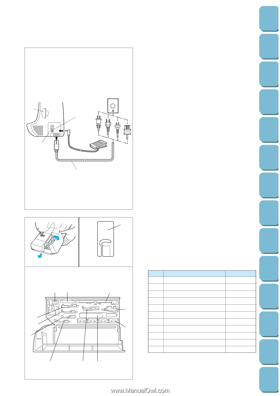
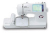
1 3 2 4 I II 2 1 III 2A 1 J 1 9 3 4 0 5 6 6 78 A. MAIN POWER SWITCH AND CONNECTORS 1 Card slot Slot for memory card insertion. 2 Main power switch Use to turn on/off the main power. 3 Controller jack Insert for foot controller operation. 4 Power cord Use to connect machine to power supply. CAUTION - When leaving the machine unattended, the main switch of the machine must be switched off or the plug must be removed from the socket-outlet. - When servicing the machine, or when removing covers or changing bulbs, the machine or the electrical set must be unplugged. - For U.S.A. only This appliance has a polarized plug (one blade wider than the other). To reduce the risk of electric shock, this plug is intended to fit in a polarized outlet only one way. If the plug does not fit fully in the outlet, reverse the plug. If it still does not fit, contact a qualified electrician to install the proper outlet. Do not modify the plug in any way. B. FLAT BED ATTACHMENT WITH ACCESSORY COMPARTMENT I Tilt the lid of the accessory compartment toward you to open. II Each presser foot has a symbol. 1 Presser foot symbol III ACCESSORY LIST The location of each accessory is shown in figure III. No. Part Name Part Code 1 Buttonhole foot "A" X57789-101 2 Embroidery foot "Q" XA5891-101 3 Overcasting foot "G" X51162-001 4 Monogramming foot "N" X53840-301 5 Zipper foot "I" X59370-051 6 Zigzag foot "J" 137748-101 7 Blind stitch foot "R" X56409-001 8 Seam ripper X54243-001 9 Button fitting foot "M" 130489-001 0 Bobbin 136492-101 A Needle set X58358-001 * Always use the plastic bobbin which is supplied with machine or in accessory compartment. * Always use BROTHER accessories recommended for this machine. Patterns (Memory Card) Patterns (Programmed in Machine) Sewing Chart Trouble shooting Error Maintenance Messages My Custom Stitch TM Retrieving Editing Embroidery Patterns Embroidering Characters and Decorative Stitches Utility Stitches Sewing Setting Up
-
 1
1 -
2
-
3
-
 4
4 -
 5
5 -
 6
6 -
 7
7 -
 8
8 -
 9
9 -
 10
10 -
 11
11 -
 12
12 -
 13
13 -
 14
14 -
15
-
16
-
17
-
18
-
19
-
20
-
21
-
22
-
23
-
24
-
25
-
26
-
27
-
28
-
29
-
30
-
31
-
32
-
33
-
34
-
35
-
36
-
37
-
38
-
39
-
40
-
41
-
42
-
43
-
44
-
45
-
46
-
47
-
48
-
49
-
50
-
51
-
52
-
53
-
54
-
55
-
56
-
57
-
58
-
59
-
60
-
61
-
62
-
63
-
64
-
65
-
66
-
67
-
68
-
69
-
70
-
71
-
72
-
73
-
74
-
75
-
76
-
77
-
78
-
79
-
80
-
81
-
82
-
83
-
84
-
85
-
86
-
87
-
88
-
89
-
90
-
91
-
92
-
93
-
94
-
95
-
96
-
97
-
98
-
99
-
100
-
101
-
102
-
103
-
104
-
105
-
106
-
107
-
108
-
109
-
110
-
111
-
112
-
113
-
114
-
115
-
116
-
117
-
118
-
119
-
120
-
121
-
122
-
123
-
124
-
125
-
126
-
127
-
128
-
129
-
130
-
131
-
132
-
133
-
134
-
135
-
136
-
137
-
138
-
139
-
140
-
141
-
142
-
143
-
144
-
145
-
146
-
147
-
148
-
149
-
150
-
151
-
152
-
153
-
154
-
155
-
156
-
157
-
158
-
159
-
160
-
161
-
162
-
163
-
164
-
165
-
166
-
167
-
168
-
169
-
170
-
171
-
172
-
173
-
174
-
175
-
176
-
177
-
178
-
179
-
180
-
181
-
182
-
183
-
184
-
185
-
186
-
187
-
188
-
189
-
190
-
191
-
192
-
193
-
194
-
195
-
196
 |
 |