Campbell Scientific 10525 ENC10/12, ENC12/14, ENC14/16, ENC16/18 Enclosures
Campbell Scientific 10525 Manual
 |
View all Campbell Scientific 10525 manuals
Add to My Manuals
Save this manual to your list of manuals |
Campbell Scientific 10525 manual content summary:
- Campbell Scientific 10525 | ENC10/12, ENC12/14, ENC14/16, ENC16/18 Enclosures - Page 1
Campbell Scientific Enclosures Revision: 8/12 Copyright © 2006-2012 Campbell Scientific, Inc. - Campbell Scientific 10525 | ENC10/12, ENC12/14, ENC14/16, ENC16/18 Enclosures - Page 2
- Campbell Scientific 10525 | ENC10/12, ENC12/14, ENC14/16, ENC16/18 Enclosures - Page 3
") to be free from defects in materials and workmanship under normal use and service for twelve (12) months from date of shipment unless otherwise specified in the corresponding Campbell pricelist or product manual. Products not manufactured, but that are re-sold by Campbell, are warranted only - Campbell Scientific 10525 | ENC10/12, ENC12/14, ENC14/16, ENC16/18 Enclosures - Page 4
435) 227-9000. After an applications engineer determines the nature of the problem, an RMA number will be issued. Please write this number clearly on 's expense. Campbell Scientific reserves the right to refuse service on products that were exposed to contaminants that may cause health or safety - Campbell Scientific 10525 | ENC10/12, ENC12/14, ENC14/16, ENC16/18 Enclosures - Page 5
Enclosures Table of Contents PDF viewers: These page numbers refer to the printed version of this document. Use the PDF reader bookmarks tab for links to specific sections. 1. General Description 1 1.1 Specifications 2 2. Enclosure Supply Kit 3 3. Mounting Equipment Inside the Enclosure 4 3.1 - Campbell Scientific 10525 | ENC10/12, ENC12/14, ENC14/16, ENC16/18 Enclosures - Page 6
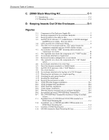
Enclosures Table of Contents C. 28960 Stack Mounting Kit C-1 C.1 Introduction C-1 C.2 Mounting Procedure C-4 D. Keeping Insects Out Of the Enclosure D-1 Figures 2-1. Components of the Enclosure Supply Kit 3 3-1. Securing components to the enclosure backplate 4 3-2. Securing cables to the cable - Campbell Scientific 10525 | ENC10/12, ENC12/14, ENC14/16, ENC16/18 Enclosures - Page 7
is easy because sensors are simply attached to prewired connectors on the outside of the enclosure. Most of the information provided in this manual pertains to the prewired enclosures. Prewired enclosures are shipped with the same enclosure supply kit (Section 2) and use the same brackets for - Campbell Scientific 10525 | ENC10/12, ENC12/14, ENC14/16, ENC16/18 Enclosures - Page 8
ENC10/12, ENC10/12R, ENC12/14, ENC14/16, ENC16/18, PWENC12/14, PWENC14/16, and PWENC16/18 1.1 Specifications Conduit Size (options "-SC", "-DC", "-VC"): 1.5 in diameter ENC10/12 Internal Dimensions: Weight: Entry Seals (option "-ES"): 25.4 x 30.5 x 11.4 cm (10 x 12 x 4.5 in) 4.1 kg (9 lb) (1) - Campbell Scientific 10525 | ENC10/12, ENC12/14, ENC14/16, ENC16/18 Enclosures - Page 9
ENC10/12, ENC10/12R, ENC12/14, ENC14/16, ENC16/18, PWENC12/14, PWENC14/16, and PWENC16/18 PWENC14/16 Internal Dimensions: Weight: PWENC16/18 Internal Dimensions: Weight: 35.6 x 40.6 x 14 cm (14 x 16 x 5.5 in) 6.2 kg (13.6 lb) 40.6 x 45.7 x 22.9 cm (16 x 18 x 9 in) 7.7 kg (17 lb) 2. Enclosure - Campbell Scientific 10525 | ENC10/12, ENC12/14, ENC14/16, ENC16/18 Enclosures - Page 10
ENC10/12, ENC10/12R, ENC12/14, ENC14/16, ENC16/18, PWENC12/14, PWENC14/16, and PWENC16/18 3. Mounting Equipment Inside the Enclosure 3.1 Enclosures with One or Two 1.5" Conduits 1. If installing the optional Door Switch Indicator, follow the procedure described in Appendix A. 2. If installing the - Campbell Scientific 10525 | ENC10/12, ENC12/14, ENC14/16, ENC16/18 Enclosures - Page 11
conduit to the datalogger and peripheral terminal strips. 5. Connect sensors and peripherals to the datalogger as described in the sensor and peripheral manuals. 6. Secure sensor and peripheral leads to the side of the enclosure using 8" cable ties and cable tie tabs (see FIGURE 3-2). The adhesive - Campbell Scientific 10525 | ENC10/12, ENC12/14, ENC14/16, ENC16/18 Enclosures - Page 12
ENC10/12, ENC10/12R, ENC12/14, ENC14/16, ENC16/18, PWENC12/14, PWENC14/16, and PWENC16/18 FIGURE 3-2. Securing cables to the cable tie tabs 6 - Campbell Scientific 10525 | ENC10/12, ENC12/14, ENC14/16, ENC16/18 Enclosures - Page 13
ENC10/12, ENC10/12R, ENC12/14, ENC14/16, ENC16/18, PWENC12/14, PWENC14/16, and PWENC16/18 FIGURE 3-3. An ENC12/14 with one 1.5" conduit houses a CR1000 datalogger and BP24 power supply. Door not shown. 3.2 Enclosures with Individual Compression Fittings 1. If installing the optional Door Switch - Campbell Scientific 10525 | ENC10/12, ENC12/14, ENC14/16, ENC16/18 Enclosures - Page 14
lead through a unique compression fitting (see FIGURE 3-4). 4. Connect sensors and peripherals to the datalogger as described in the sensor and peripheral manuals. 5. Secure sensor and peripheral leads to the side of the enclosure using 8" cable ties and cable tie tabs (see FIGURE 3-2). The - Campbell Scientific 10525 | ENC10/12, ENC12/14, ENC14/16, ENC16/18 Enclosures - Page 15
ENC10/12, ENC10/12R, ENC12/14, ENC14/16, ENC16/18, PWENC12/14, PWENC14/16, and PWENC16/18 4" Cable Tie Secures Cable to CR1000 Compression Fittings FIGURE 3-5. This ENC16/18 enclosure with the "-ES" option houses the equipment commonly used in a GOES satellite system 4. Attachment to an Instrument - Campbell Scientific 10525 | ENC10/12, ENC12/14, ENC14/16, ENC16/18 Enclosures - Page 16
ENC10/12, ENC10/12R, ENC12/14, ENC14/16, ENC16/18, PWENC12/14, PWENC14/16, and PWENC16/18 FIGURE 4-1. An enclosure with the "-MM" mounting option attaches to a tripod mast via u-bolts FIGURE 4-2. This exploded view shows the components of a "-MM" bracket 10 - Campbell Scientific 10525 | ENC10/12, ENC12/14, ENC14/16, ENC16/18 Enclosures - Page 17
ENC10/12, ENC10/12R, ENC12/14, ENC14/16, ENC16/18, PWENC12/14, PWENC14/16, and PWENC16/18 FIGURE 4-3. An enclosure attached to a tripod mast 4.2 UT10 10 ft Tower The "-TM" option is used to attach our enclosures to a UT10 tower. An enclosure ordered with the "-TM" option will be shipped with a three - Campbell Scientific 10525 | ENC10/12, ENC12/14, ENC14/16, ENC16/18 Enclosures - Page 18
ENC10/12, ENC10/12R, ENC12/14, ENC14/16, ENC16/18, PWENC12/14, PWENC14/16, and PWENC16/18 NOTE same three-piece brackets as the "-MM" option, except the pieces are rearranged so that the flanges are on the side of the bracket instead of in the middle. The distance between the centers of each - Campbell Scientific 10525 | ENC10/12, ENC12/14, ENC14/16, ENC16/18 Enclosures - Page 19
ENC10/12, ENC10/12R, ENC12/14, ENC14/16, ENC16/18, PWENC12/14, PWENC14/16, and PWENC16/18 The default configuration is for attaching to a UT10 tower (i.e., D = 10.25"). To attach to a UT20 or UT30 tower, move the flange sections of the bracket so that D = 17". Flange Section Flange Section FIGURE - Campbell Scientific 10525 | ENC10/12, ENC12/14, ENC14/16, ENC16/18 Enclosures - Page 20
ENC10/12, ENC10/12R, ENC12/14, ENC14/16, ENC16/18, PWENC12/14, PWENC14/16, and PWENC16/18 4.4 Tripod Leg Base The "-LM" mount option is intended for attaching an enclosure to the leg base of a CM106, CM106K, CM110, CM115, or CM120 tripod. NOTE The ENC16/18 can be mounted to the leg base of a - Campbell Scientific 10525 | ENC10/12, ENC12/14, ENC14/16, ENC16/18 Enclosures - Page 21
ENC10/12, ENC10/12R, ENC12/14, ENC14/16, ENC16/18, PWENC12/14, PWENC14/16, and PWENC16/18 Flange FIGURE 4-7. The 19124 bracket attached to a CM110 tripod Notch FIGURE 4-8. An ENC14/16 enclosure with a "-LM" Bracket 15 - Campbell Scientific 10525 | ENC10/12, ENC12/14, ENC14/16, ENC16/18 Enclosures - Page 22
ENC10/12, ENC10/12R, ENC12/14, ENC14/16, ENC16/18, PWENC12/14, PWENC14/16, and PWENC16/18 FIGURE 4-9. The u-bolt bracket FIGURE 4-10. An enclosure attached to the leg base of a CM110 tripod 16 - Campbell Scientific 10525 | ENC10/12, ENC12/14, ENC14/16, ENC16/18 Enclosures - Page 23
ENC10/12, ENC10/12R, ENC12/14, ENC14/16, ENC16/18, PWENC12/14, PWENC14/16, and PWENC16/18 4.4.1 Mounting More Than One Enclosure on a Tripod Leg (CM110, CM115, CM120) It is possible to mount two enclosures back-to-back on the CM110, CM115, and CM120 tripods. If the enclosures are different sizes, - Campbell Scientific 10525 | ENC10/12, ENC12/14, ENC14/16, ENC16/18 Enclosures - Page 24
ENC10/12, ENC10/12R, ENC12/14, ENC14/16, ENC16/18, PWENC12/14, PWENC14/16, and PWENC16/18 Enclosure Bracket Washer Bolt LockNut FIGURE 4-12. Attaching the pole mount bracket 2. Feed a metal band through the openings in each bracket as shown in FIGURE 4-13. Use the closest set of holes for - Campbell Scientific 10525 | ENC10/12, ENC12/14, ENC14/16, ENC16/18 Enclosures - Page 25
ENC10/12, ENC10/12R, ENC12/14, ENC14/16, ENC16/18, PWENC12/14, PWENC14/16, and PWENC16/18 5. Insert the tab on the end of the Screw Threads (FIGURE 4-14) into the hole at one end of the upper strap. Enclosure Mounting Pole Band Screw Threads Screw Clamp FIGURE 4-14. Securing the enclosure to a - Campbell Scientific 10525 | ENC10/12, ENC12/14, ENC14/16, ENC16/18 Enclosures - Page 26
humidity inside an enclosure. When the measurements exceed 35% relative humidity, replace the desiccant packets. Refer to the CS210 manual for sensor specifications, installation procedures, and programming information. 6. Resistance to Weathering Our enclosures are coated to protect them from - Campbell Scientific 10525 | ENC10/12, ENC12/14, ENC14/16, ENC16/18 Enclosures - Page 27
ENC10/12, ENC10/12R, ENC12/14, ENC14/16, ENC16/18, PWENC12/14, PWENC14/16, and PWENC16/18 CAUTION 3. Use a fine grain sandpaper to gently sand the enclosure surface; if the surface of the enclosure is sufficiently rough, this step may be skipped. 4. Spray with clear acrylic paint. Properly - Campbell Scientific 10525 | ENC10/12, ENC12/14, ENC14/16, ENC16/18 Enclosures - Page 28
ENC10/12, ENC10/12R, ENC12/14, ENC14/16, ENC16/18, PWENC12/14, PWENC14/16, and PWENC16/18 22 - Campbell Scientific 10525 | ENC10/12, ENC12/14, ENC14/16, ENC16/18 Enclosures - Page 29
to mount the sensor and magnet to the enclosure case and door. Which brackets are used depends on the style of enclosure. Use the following guide to determine the proper brackets: a. The Door Open Indicator is mounted at the upper right corner of the enclosure. The enclosure DOOR determines which - Campbell Scientific 10525 | ENC10/12, ENC12/14, ENC14/16, ENC16/18 Enclosures - Page 30
Appendix A. Door Switch Sensor c. The bracket used for mounting the sensor magnet in the door depends on the depth of the door. If the door face is flat, the sensor magnet is mounted as shown below. Large Bracket Insert Large Bracket d. If the door face is extended, the sensor magnet is mounted as - Campbell Scientific 10525 | ENC10/12, ENC12/14, ENC14/16, ENC16/18 Enclosures - Page 31
Appendix A. Door Switch 3. Assemble the sensor magnet with the bracket determined in step 1. Place the bracket in position so the edge of the sensor magnet does not extend beyond the internal edge of the door. Mark the locations for two mounting holes to secure the sensor magnet bracket. Important: - Campbell Scientific 10525 | ENC10/12, ENC12/14, ENC14/16, ENC16/18 Enclosures - Page 32
Appendix A. Door Switch 7. Place the assembled sensor bracket over the two screws, making sure the sensor is aligned with the inside edge of the case. Secure the bracket in place with two lock-nuts. Enclosure Mounting Bracket Screw Lock Nut Sensor 8. From the outside of the enclosure door, insert - Campbell Scientific 10525 | ENC10/12, ENC12/14, ENC14/16, ENC16/18 Enclosures - Page 33
interval If TimeInToInterval(0,5,Min) Then DOOR_output = 0 EndIf ' Method #2: Door open status may be recorded as a fraction of the output ' interval (between 0 and 1) using the Histogram instruction. CallTable Table102 NextScan EndProg A-5 - Campbell Scientific 10525 | ENC10/12, ENC12/14, ENC14/16, ENC16/18 Enclosures - Page 34
Door open status may be recorded as a fraction of the output interval ; (between 0 and 1) using the Histogram instruction. ; Method #1 7: If (XF) (P89) 1: X Loc [ DOORopen1 ] 2: 1 = 3: 1 F 4: 30 Then Do 8: Z=F x 10^n (P30) 1: 1 F 2: 00 n, Exponent of 10 3: 2 Z Loc [ DOOR_out - Campbell Scientific 10525 | ENC10/12, ENC12/14, ENC14/16, ENC16/18 Enclosures - Page 35
Appendix A. Door Switch 9: End (P95) 10: If time is (P92) 1: 0 Minutes (Seconds --) into a 2: 5 Interval (same units as above) 3: 10 Set Output Flag High (Flag 0) 11: Set Active Storage Area (P80) 1: 1 Final Storage Area 1 2: 101 Array ID 12: Sample (P70) 1: 1 Reps 2: 2 Loc [ - Campbell Scientific 10525 | ENC10/12, ENC12/14, ENC14/16, ENC16/18 Enclosures - Page 36
Appendix A. Door Switch A-8 - Campbell Scientific 10525 | ENC10/12, ENC12/14, ENC14/16, ENC16/18 Enclosures - Page 37
Appendix B. 25458/28532 DIN-Rail Terminal Kits B.1 Introduction The 25458 (5-inch) or 28532 (9-inch) kit can facilitate wiring when many wires need to be connected to one terminal. The kit contains one 15906 5-inch DIN-Rail (or one 28531 9-inch DIN-Rail) Mounting Bracket, 505 screws, 6044 grommets, - Campbell Scientific 10525 | ENC10/12, ENC12/14, ENC14/16, ENC16/18 Enclosures - Page 38
Appendix B. 25458/28532 DIN-Rail Terminal Kits FIGURE B-2. 15920 Terminal Strip installation FIGURE B-3. 15907 End Plate installation B-2 - Campbell Scientific 10525 | ENC10/12, ENC12/14, ENC14/16, ENC16/18 Enclosures - Page 39
Appendix B. 25458/28532 DIN-Rail Terminal Kits 2. Insert the 15909 Jumpers in the terminal strips as shown in FIGURE B-4. NOTE FIGURE B-4. 15909 Jumper installation 3. Mount the DIN-Rail bracket onto the enclosure backplate using two 505 screws and two 6044 grommets (see FIGURE B-5). The 28532 - Campbell Scientific 10525 | ENC10/12, ENC12/14, ENC14/16, ENC16/18 Enclosures - Page 40
Appendix B. 25458/28532 DIN-Rail Terminal Kits 4. Connect the wires to the terminals (see FIGURE B-6 and FIGURE B-7). The 8125 flat-bladed screwdriver is used to open the terminals' guillotines for wire entry. FIGURE B-6. An installed and wired 25458 DIN-Rail Terminal Kit FIGURE B-7. The 25458 DIN- - Campbell Scientific 10525 | ENC10/12, ENC12/14, ENC14/16, ENC16/18 Enclosures - Page 41
Appendix C. 28960 Stack Mounting Kit C.1 Introduction The 28960 Stack Mounting Kit is used to raise a component 3 in above the surface of the back plate. This is beneficial when an enclosure nears its holding capacity of components. Using the Stack Mounting Kit allows one component to be stacked - Campbell Scientific 10525 | ENC10/12, ENC12/14, ENC14/16, ENC16/18 Enclosures - Page 42
Appendix C. 28960 Stack Mounting Kit Enclosure Back Plate AM16/32B Leg Top Grid CR1000 Leg FIGURE C-2. Assembled view of CR1000 and AM16/32B mounted on a 28960 Stack Mounting Kit The Stack Mounting Kit consists of a Top Grid, two Legs, eight Grommets, and eight Screws (FIGURE C-3). Besides the - Campbell Scientific 10525 | ENC10/12, ENC12/14, ENC14/16, ENC16/18 Enclosures - Page 43
Appendix C. 28960 Stack Mounting Kit Grommet Screw (8) Leg (8) Leg Top Grid FIGURE C-3. Contents of 28960 Stacking Kit FIGURE C-4. CR1000 mounted to Stack Mounting Kit legs C-3 - Campbell Scientific 10525 | ENC10/12, ENC12/14, ENC14/16, ENC16/18 Enclosures - Page 44
Appendix C. 28960 Stack Mounting Kit C.2 Mounting Procedure 1. Determine the spacing needed between the two legs. 2. Secure the legs to the back plate using screws and grommets. If a component is to be mounted under another and shares the same mounting holes as the leg, mount the pieces in the - Campbell Scientific 10525 | ENC10/12, ENC12/14, ENC14/16, ENC16/18 Enclosures - Page 45
Appendix D. Keeping Insects Out Of the Enclosure Campbell Scientific has published an application note regarding how to keep pests away from the equipment. It is found on the Campbell Scientific website (www.campbellsci.com/app-notes) and is called "Keeping Pests Away from Equipment (5-Y)." Here - Campbell Scientific 10525 | ENC10/12, ENC12/14, ENC14/16, ENC16/18 Enclosures - Page 46
Appendix D. Keeping Insects Out Of the Enclosure D-2 - Campbell Scientific 10525 | ENC10/12, ENC12/14, ENC14/16, ENC16/18 Enclosures - Page 47
- Campbell Scientific 10525 | ENC10/12, ENC12/14, ENC14/16, ENC16/18 Enclosures - Page 48
Campbell Scientific Companies Campbell Scientific, Inc. (CSI) 815 West 1800 North Logan, Utah 84321 UNITED STATES www.campbellsci.com • [email protected] Campbell Scientific Africa Pty. Ltd. (CSAf) PO Box 2450 Somerset West 7129 SOUTH AFRICA www.csafrica.co.za • [email protected] Campbell
-
 1
1 -
 2
2 -
 3
3 -
 4
4 -
 5
5 -
 6
6 -
 7
7 -
8
-
9
-
10
-
11
-
12
-
13
-
14
-
15
-
16
-
17
-
18
-
19
-
20
-
21
-
22
-
23
-
24
-
25
-
26
-
27
-
28
-
29
-
30
-
31
-
32
-
33
-
34
-
35
-
36
-
37
-
38
-
39
-
40
-
41
-
42
-
43
-
44
-
45
-
46
-
47
-
48
 |
 |

Campbell Scientific Enclosures
Revision: 8/12
Copyright © 2006-2012
Campbell Scientific, Inc.