Campbell Scientific 10525 ENC10/12, ENC12/14, ENC14/16, ENC16/18 Enclosures - Page 19
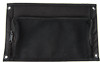
Flange An enclosure attached to two tower legs
 |
View all Campbell Scientific 10525 manuals
Add to My Manuals
Save this manual to your list of manuals |
Page 19 highlights
ENC10/12, ENC10/12R, ENC12/14, ENC14/16, ENC16/18, PWENC12/14, PWENC14/16, and PWENC16/18 The default configuration is for attaching to a UT10 tower (i.e., D = 10.25"). To attach to a UT20 or UT30 tower, move the flange sections of the bracket so that D = 17". Flange Section Flange Section FIGURE 4-5. This exploded view shows the components of a "-TM" bracket option FIGURE 4-6. An enclosure attached to two tower legs 13
-
 1
1 -
2
-
3
-
4
-
5
-
6
-
7
-
8
-
9
-
10
-
11
-
12
-
13
-
 14
14 -
 15
15 -
 16
16 -
 17
17 -
 18
18 -
 19
19 -
 20
20 -
 21
21 -
 22
22 -
 23
23 -
 24
24 -
25
-
26
-
27
-
28
-
29
-
30
-
31
-
32
-
33
-
34
-
35
-
36
-
37
-
38
-
39
-
40
-
41
-
42
-
43
-
44
-
45
-
46
-
47
-
48
 |
 |

ENC10/12, ENC10/12R, ENC12/14, ENC14/16, ENC16/18, PWENC12/14, PWENC14/16, and PWENC16/18
The default configuration is for attaching to a UT10 tower (i.e., D = 10.25").
To attach to a UT20 or UT30 tower, move the flange sections of the bracket so
that D = 17".
Flange Section
Flange Section
FIGURE 4-5.
This exploded view shows the components of
a “-TM” bracket option
FIGURE 4-6.
An enclosure attached to two tower legs
13