Campbell Scientific 10525 ENC10/12, ENC12/14, ENC14/16, ENC16/18 Enclosures - Page 32
holes in the enclosure door., Place the assembled sensor magnet bracket over the two screws, making
 |
View all Campbell Scientific 10525 manuals
Add to My Manuals
Save this manual to your list of manuals |
Page 32 highlights
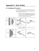
Appendix A. Door Switch 7. Place the assembled sensor bracket over the two screws, making sure the sensor is aligned with the inside edge of the case. Secure the bracket in place with two lock-nuts. Enclosure Mounting Bracket Screw Lock Nut Sensor 8. From the outside of the enclosure door, insert two screws through the new holes in the enclosure door. 9. Place the assembled sensor magnet bracket over the two screws, making sure the sensor magnet is aligned with the inside edge of the door. Secure the bracket in place with two lock-nuts. A-4
-
 1
1 -
2
-
3
-
4
-
5
-
6
-
7
-
8
-
9
-
10
-
11
-
12
-
13
-
14
-
15
-
16
-
17
-
18
-
19
-
20
-
21
-
22
-
23
-
24
-
25
-
26
-
 27
27 -
 28
28 -
 29
29 -
 30
30 -
 31
31 -
 32
32 -
 33
33 -
 34
34 -
 35
35 -
 36
36 -
 37
37 -
38
-
39
-
40
-
41
-
42
-
43
-
44
-
45
-
46
-
47
-
48
 |
 |

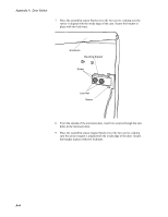
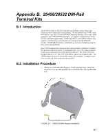
Appendix A.
Door Switch
7.
Place the assembled sensor bracket over the two screws, making sure the
sensor is aligned with the inside edge of the case. Secure the bracket in
place with two lock-nuts.
Mounting Bracket
Enclosure
Sensor
Screw
Lock Nut
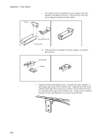
8.
From the outside of the enclosure door, insert two screws through the new
holes in the enclosure door.
9.
Place the assembled sensor magnet bracket over the two screws, making
sure the sensor magnet is aligned with the inside edge of the door. Secure
the bracket in place with two lock-nuts.
A-4