Campbell Scientific 10525 ENC10/12, ENC12/14, ENC14/16, ENC16/18 Enclosures - Page 30
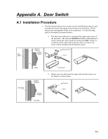
Appendix A., Door Switch, in the upper right corner of the enclosure case.
 |
View all Campbell Scientific 10525 manuals
Add to My Manuals
Save this manual to your list of manuals |
Page 30 highlights
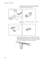
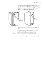
Appendix A. Door Switch Sensor c. The bracket used for mounting the sensor magnet in the door depends on the depth of the door. If the door face is flat, the sensor magnet is mounted as shown below. Large Bracket Insert Large Bracket d. If the door face is extended, the sensor magnet is mounted as shown below. Small Bracket Magnet 2. Using the brackets determined in step 1, assemble the sensor and place it in the upper right corner of the enclosure case. Align the top of the sensor with the inside edge of the sensor case as shown. Do not allow the sensor to extend beyond the edge of the enclosure case. Using a marker, mark the locations for two mounting holes to secure the sensor bracket. A-2
-
 1
1 -
2
-
3
-
4
-
5
-
6
-
7
-
8
-
9
-
10
-
11
-
12
-
13
-
14
-
15
-
16
-
17
-
18
-
19
-
20
-
21
-
22
-
23
-
24
-
 25
25 -
 26
26 -
 27
27 -
 28
28 -
 29
29 -
 30
30 -
 31
31 -
 32
32 -
 33
33 -
 34
34 -
 35
35 -
36
-
37
-
38
-
39
-
40
-
41
-
42
-
43
-
44
-
45
-
46
-
47
-
48
 |
 |

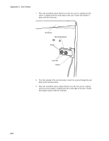
Appendix A.
Door Switch
c.
The bracket used for mounting the sensor magnet in the door
depends on the depth of the door.
If the door face is flat, the
sensor magnet is mounted as shown below.
Large Bracket
Sensor
Large Bracket Insert
d.
If the door face is extended, the sensor magnet is mounted as
shown below.
Small Bracket
Magnet
2.
Using the brackets determined in step 1, assemble the sensor and place it
in the upper right corner of the enclosure case.
Align the top of the sensor
with the inside edge of the sensor case as shown.
Do not allow the sensor
to extend beyond the edge of the enclosure case.
Using a marker, mark the
locations for two mounting holes to secure the sensor bracket.
A-2