Campbell Scientific 10525 ENC10/12, ENC12/14, ENC14/16, ENC16/18 Enclosures - Page 6

Stack Mounting Kit, Keeping Insects Out Of the Enclosure, s

Page 6 highlights

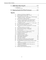
Enclosures Table of Contents C. 28960 Stack Mounting Kit C-1 C.1 Introduction C-1 C.2 Mounting Procedure C-4 D. Keeping Insects Out Of the Enclosure D-1 Figures 2-1. Components of the Enclosure Supply Kit 3 3-1. Securing components to the enclosure backplate 4 3-2. Securing cables to the cable tie tabs 6 3-3. An ENC12/14 with one 1.5" conduit houses a CR1000 datalogger and BP24 power supply. Door not shown 7 3-4. Cable inserted into compression fitting 8 3-5. This ENC16/18 enclosure with the "-ES" option houses the equipment commonly used in a GOES satellite system 9 4-1. An enclosure with the "-MM" mounting option attaches to a tripod mast via u-bolts 10 4-2. This exploded view shows the components of a "-MM" bracket ...... 10 4-3. An enclosure attached to a tripod mast 11 4-4. Enclosure brackets configured for a tower mount 12 4-5. This exploded view shows the components of a "-TM" bracket option 13 4-6. An enclosure attached to two tower legs 13 4-7. The 19124 bracket attached to a CM110 tripod 15 4-8. An ENC14/16 enclosure with a "-LM" Bracket 15 4-9. The u-bolt bracket 16 4-10. An enclosure attached to the leg base of a CM110 tripod 16 4-11. Mounting two enclosures on a single tripod leg 17 4-12. Attaching the pole mount bracket 18 4-13. Inserting the metal band 18 4-14. Securing the enclosure to a pole 19 B-1. 15908 DIN-Rail Stopper installation B-1 B-2. 15920 Terminal Strip installation B-2 B-3. 15907 End Plate installation B-2 B-4. 15909 Jumper installation B-3 B-5. DIN-Rail bracket mounted onto an enclosure backplate B-3 B-6. An installed and wired 25458 DIN-Rail Terminal Kit B-4 B-7. The 25458 DIN-Rail Terminal Kit facilitates wiring of multiple sensors B-4 C-1. Exploded view of a CR1000 and AM16/32B mounted on a 28960 Stack Mounting Kit C-1 C-2. Assembled view of CR1000 and AM16/32B mounted on a 28960 Stack Mounting Kit C-2 C-3. Contents of 28960 Stacking Kit C-3 C-4. CR1000 mounted to Stack Mounting Kit legs C-3 ii

  • 1
  • 2
  • 3
  • 4
  • 5
  • 6
  • 7
  • 8
  • 9
  • 10
  • 11
  • 12
  • 13
  • 14
  • 15
  • 16
  • 17
  • 18
  • 19
  • 20
  • 21
  • 22
  • 23
  • 24
  • 25
  • 26
  • 27
  • 28
  • 29
  • 30
  • 31
  • 32
  • 33
  • 34
  • 35
  • 36
  • 37
  • 38
  • 39
  • 40
  • 41
  • 42
  • 43
  • 44
  • 45
  • 46
  • 47
  • 48

Enclosures Table of Contents
ii
C.
28960 Stack Mounting Kit
.......................................
C-1
C.1
Introduction
.........................................................................................
C-1
C.2
Mounting Procedure
............................................................................
C-4
D.
Keeping Insects Out Of the Enclosure
..................
D-1
Figures
2-1.
Components of the Enclosure Supply Kit
...........................................
3
3-1.
Securing components to the enclosure backplate
................................
4
3-2.
Securing cables to the cable tie tabs
....................................................
6
3-3.
An ENC12/14 with one 1.5" conduit houses a CR1000 datalogger
and BP24 power supply. Door not shown
.......................................
7
3-4.
Cable inserted into compression fitting
...............................................
8
3-5.
This ENC16/18 enclosure with the “-ES” option houses the
equipment commonly used in a GOES satellite system
...................
9
4-1.
An enclosure with the “-MM” mounting option attaches to a
tripod mast via u-bolts
..................................................................
10
4-2.
This exploded view shows the components of a “-MM” bracket
......
10
4-3.
An enclosure attached to a tripod mast
..............................................
11
4-4.
Enclosure brackets configured for a tower mount
.............................
12
4-5.
This exploded view shows the components of a “-TM” bracket
option
.............................................................................................
13
4-6.
An enclosure attached to two tower legs
...........................................
13
4-7.
The 19124 bracket attached to a CM110 tripod
................................
15
4-8.
An ENC14/16 enclosure with a “-LM” Bracket
................................
15
4-9.
The u-bolt bracket
.............................................................................
16
4-10.
An enclosure attached to the leg base of a CM110 tripod
.................
16
4-11.
Mounting two enclosures on a single tripod leg
................................
17
4-12.
Attaching the pole mount bracket
......................................................
18
4-13.
Inserting the metal band
....................................................................
18
4-14.
Securing the enclosure to a pole
........................................................
19
B-1.
15908 DIN-Rail Stopper installation
...............................................
B-1
B-2.
15920 Terminal Strip installation
....................................................
B-2
B-3.
15907 End Plate installation
............................................................
B-2
B-4.
15909 Jumper installation
................................................................
B-3
B-5.
DIN-Rail bracket mounted onto an enclosure backplate
.................
B-3
B-6.
An installed and wired 25458 DIN-Rail Terminal Kit
....................
B-4
B-7.
The 25458 DIN-Rail Terminal Kit facilitates wiring of multiple
sensors
..........................................................................................
B-4
C-1.
Exploded view of a CR1000 and AM16/32B mounted on a
28960 Stack Mounting Kit
...........................................................
C-1
C-2.
Assembled view of CR1000 and AM16/32B mounted on a
28960 Stack Mounting Kit
...........................................................
C-2
C-3.
Contents of 28960 Stacking Kit
.......................................................
C-3
C-4.
CR1000 mounted to Stack Mounting Kit legs
.................................
C-3