Canon DIGISUPER 60 xs manual for XJ100x9.3B AF XJ100x9.3B XJ95x12.4B XJ95x8.6B - Page 46
Mounting the AF Auto Focus Demand, Only Models with AF Function, Mounting the Accessories for IS,
 |
View all Canon DIGISUPER 60 xs manuals
Add to My Manuals
Save this manual to your list of manuals |
Page 46 highlights
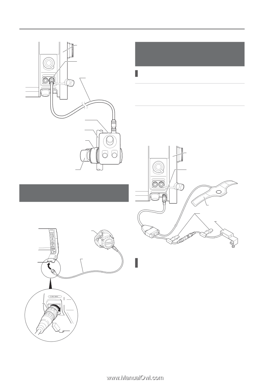
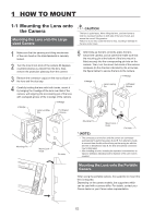
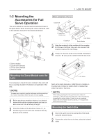
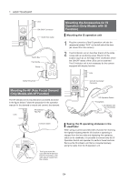
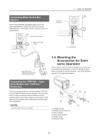
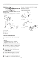
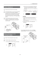
1 HOW TO MOUNT Lens "SW. BOX" Connector Switch Box Cable Switch Box Pan Handle Clamp Mounting the Accessories for IS Operation (Only Models with IS Function) Mounting the IS operation unit 1 Plug the connector of the IS operation unit into the receptacle labeled "AUX" on the left side of the lens (as viewed from the camera). 2 The IS Indicator unit on the other branch of the cable comes with an anchoring screw. Mount it to the location (such as on the edge of the viewfinder) where the ON/OFF status of the LEDs can be observed. The IS indicator unit is not necessary for the camera equipped with display function. Lens Clamp fixing knob Mounting the AF (Auto Focus) Demand (Only Models with AF Function) The AF demand unit is mounted and connected as shown in the figure below. Follow the procedure in the operation manual for the demand to mount and connect the demand. Lens AF Demand FDJ-P41 "AUX (IS Controller)" Connector IS Operation Switch Fixing Belts IS Indicator Unit (or Viewfinder) Fixing Ring Demand Cable Lock • This figure shows the case with the AF demand FDJ-P41 mounted on the right side as viewed from the camera. Seeing the IS operating statuses in the viewfinder When using a camera provided with a function for receiving the signals indicating that the IS function is operating or stopped from the lens side and displaying this operating status on its viewfinder, it is possible to connect only the IS Operation Switch and operate it to perform these functions. Remove the IS indicator unit that is connected partway along the cable from the IS operation unit. E4
-
 1
1 -
2
-
3
-
4
-
5
-
6
-
7
-
8
-
9
-
10
-
11
-
12
-
13
-
14
-
15
-
16
-
17
-
18
-
19
-
20
-
21
-
22
-
23
-
24
-
25
-
26
-
27
-
28
-
29
-
30
-
31
-
32
-
33
-
34
-
35
-
36
-
37
-
38
-
39
-
40
-
 41
41 -
 42
42 -
 43
43 -
 44
44 -
 45
45 -
 46
46 -
 47
47 -
 48
48 -
 49
49 -
 50
50 -
 51
51 -
52
-
53
-
54
-
55
-
56
-
57
-
58
-
59
-
60
-
61
-
62
-
63
-
64
-
65
-
66
-
67
-
68
-
69
-
70
-
71
-
72
-
73
-
74
-
75
-
76
-
77
-
78
-
79
-
80
-
81
-
82
-
83
-
84
-
85
-
86
-
87
-
88
-
89
-
90
-
91
-
92
-
93
-
94
-
95
-
96
-
97
-
98
-
99
-
100
-
101
-
102
-
103
-
104
-
105
-
106
-
107
-
108
-
109
-
110
-
111
-
112
-
113
-
114
-
115
-
116
-
117
-
118
-
119
-
120
-
121
-
122
-
123
-
124
-
125
-
126
-
127
-
128
-
129
-
130
-
131
-
132
-
133
-
134
-
135
-
136
 |
 |