Canon DIGISUPER 60 xs manual for XJ100x9.3B AF XJ100x9.3B XJ95x12.4B XJ95x8.6B - Page 60
Other Functions and Options
 |
View all Canon DIGISUPER 60 xs manuals
Add to My Manuals
Save this manual to your list of manuals |
Page 60 highlights
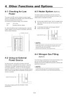
4 Other Functions and Options 4-1 Checking for Low Power The power low LED, used to indicate low power supply warning, is provided on the indicator panel at the left side of the lens, as viewed from the camera. According to the supplied voltage, LED indicates: Lit red: Off: 10V or less Supplies sufficient voltage So, when the LED is lit red, countermeasures to raise the supply voltage to 10.5V or above is necessary. Otherwise, the lens may malfunction. POWER LOW LED 4-3 Heater System (Option) The heater system for warming up the lens to prevent clouding inside the lens can be mounted on the lens. The heater system is operated as follows. 1 Set the heater ON/OFF switch, which is located on the right side of the lens as seen from the camera, to the ON position. 2 To shut down the heater, set the heater ON/OFF switch to the OFF position. Heater ON/OFF Switch * (NOTE) A great deal of power is consumed when the heater switch is ON. For this reason, the circuitry is designed to disable servo zoom operations and servo focus operations. To perform servo operations, stop using the heater. 4-2 Using an External Power Source An external power input jack is provided at the right side of the lens, as viewed from the camera. In case the combination of portable camera and the lens with semi or full servo operation, 12V DC (11-17V DC) should be supplied to the lens through this jack since portable camera does not have enough power consumption to drive semi or full servo operation. 4-4 Nitrogen Gas Filling (Option) To prevent fog or condensation on the internal surface of the lens, you can fill the lens barrel with nitrogen gas. Nitrogen gas should be refilled at the periodic overhaul, and before the critical event. * (NOTE) To refill nitrogen gas, gas canister and filling tool are required. Contact your Canon dealer or your Canon sales representative. External Power Input Jack Use a plug complying with EIAJ RC5320A TYPE4 specifications. E18
-
 1
1 -
2
-
3
-
4
-
5
-
6
-
7
-
8
-
9
-
10
-
11
-
12
-
13
-
14
-
15
-
16
-
17
-
18
-
19
-
20
-
21
-
22
-
23
-
24
-
25
-
26
-
27
-
28
-
29
-
30
-
31
-
32
-
33
-
34
-
35
-
36
-
37
-
38
-
39
-
40
-
41
-
42
-
43
-
44
-
45
-
46
-
47
-
48
-
49
-
50
-
51
-
52
-
53
-
54
-
 55
55 -
 56
56 -
 57
57 -
 58
58 -
 59
59 -
 60
60 -
 61
61 -
 62
62 -
 63
63 -
 64
64 -
 65
65 -
66
-
67
-
68
-
69
-
70
-
71
-
72
-
73
-
74
-
75
-
76
-
77
-
78
-
79
-
80
-
81
-
82
-
83
-
84
-
85
-
86
-
87
-
88
-
89
-
90
-
91
-
92
-
93
-
94
-
95
-
96
-
97
-
98
-
99
-
100
-
101
-
102
-
103
-
104
-
105
-
106
-
107
-
108
-
109
-
110
-
111
-
112
-
113
-
114
-
115
-
116
-
117
-
118
-
119
-
120
-
121
-
122
-
123
-
124
-
125
-
126
-
127
-
128
-
129
-
130
-
131
-
132
-
133
-
134
-
135
-
136
 |
 |
