Canon DIGISUPER 60 xs manual for XJ100x9.3B AF XJ100x9.3B XJ95x12.4B XJ95x8.6B - Page 56
Iris Operation
 |
View all Canon DIGISUPER 60 xs manuals
Add to My Manuals
Save this manual to your list of manuals |
Page 56 highlights
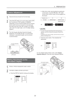
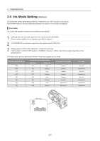
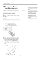
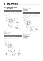
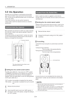
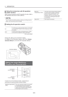
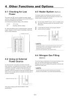
3 OPERATION 3-2 Iris Operation Normally, lens iris operation is performed by the position servo control method using commands from the camera CCU. Control can be switched between auto iris control and remote iris control. The camera operator can also perform remote iris control using a switch box (special version) as a special specification. Control from the Camera Control from the Switch Box When a switch box which is capable to control the iris function of the lens is mounted, the iris function of the lens is controlled by it. Setting the iris control select switch Settings must be performed at the lens side in order for the iris to be controlled from the switch box. Follow the setting steps below. Both automatic and remote iris control are usually operated from the CCU. (Refer to the camera operation manual on how to operate.) During the shooting, an approximate F number (iris value) can be checked with the indicator panel on the left side of the lens, as viewed from the camera. F Number Indicator 1 Remove the lens shroud. 2 Change the DIP switch setting to the "ON" position (I.LOCAL). Controlling Control the iris by turning the iris control knob as set forth below. Turning the knob clockwise: The iris moves in the opening direction. Turning the knob counterclockwise: The iris moves in the closing direction. Iris Control Knob The value indicated by the indicator varies depending on the model. Setting the iris control select switch The DIP switch (SW2) No. 4 was set to the "OFF" position (I.CAMERA) at the factory prior to shipment so that the iris can be operated from the camera. If the iris operation is disabled, follow the steps below to check the setting position of DIP switch (SW2) No. 4. "OFF" position: Iris operation is enabled from the camera. "ON" position: Iris operation is enabled from such as switch box. 1 Remove the lens shroud. 2 Check that DIP switch is set to the "OFF" position. If the switch is set to "ON" position, change the setting to the "OFF" position. As when the iris is to be controlled from the camera, the approximate F number can be monitored on the indicator panel. * (NOTE) • See the section "Mounting the Switch Box" (p. E3) for details of how to mount and connect the switch box. • Refer to the table "Iris mode" in the section 2-5 "Iris Mode Setting (Option)" to understand the relationship among the command signals from camera, iris control device, and the position of the iris control select switch. E14
-
 1
1 -
2
-
3
-
4
-
5
-
6
-
7
-
8
-
9
-
10
-
11
-
12
-
13
-
14
-
15
-
16
-
17
-
18
-
19
-
20
-
21
-
22
-
23
-
24
-
25
-
26
-
27
-
28
-
29
-
30
-
31
-
32
-
33
-
34
-
35
-
36
-
37
-
38
-
39
-
40
-
41
-
42
-
43
-
44
-
45
-
46
-
47
-
48
-
49
-
50
-
 51
51 -
 52
52 -
 53
53 -
 54
54 -
 55
55 -
 56
56 -
 57
57 -
 58
58 -
 59
59 -
 60
60 -
 61
61 -
62
-
63
-
64
-
65
-
66
-
67
-
68
-
69
-
70
-
71
-
72
-
73
-
74
-
75
-
76
-
77
-
78
-
79
-
80
-
81
-
82
-
83
-
84
-
85
-
86
-
87
-
88
-
89
-
90
-
91
-
92
-
93
-
94
-
95
-
96
-
97
-
98
-
99
-
100
-
101
-
102
-
103
-
104
-
105
-
106
-
107
-
108
-
109
-
110
-
111
-
112
-
113
-
114
-
115
-
116
-
117
-
118
-
119
-
120
-
121
-
122
-
123
-
124
-
125
-
126
-
127
-
128
-
129
-
130
-
131
-
132
-
133
-
134
-
135
-
136
 |
 |