Canon DIGISUPER 60 xs manual for XJ100x9.3B AF XJ100x9.3B XJ95x12.4B XJ95x8.6B - Page 47
Mounting the, Accessories for Semi, servo Operation
 |
View all Canon DIGISUPER 60 xs manuals
Add to My Manuals
Save this manual to your list of manuals |
Page 47 highlights
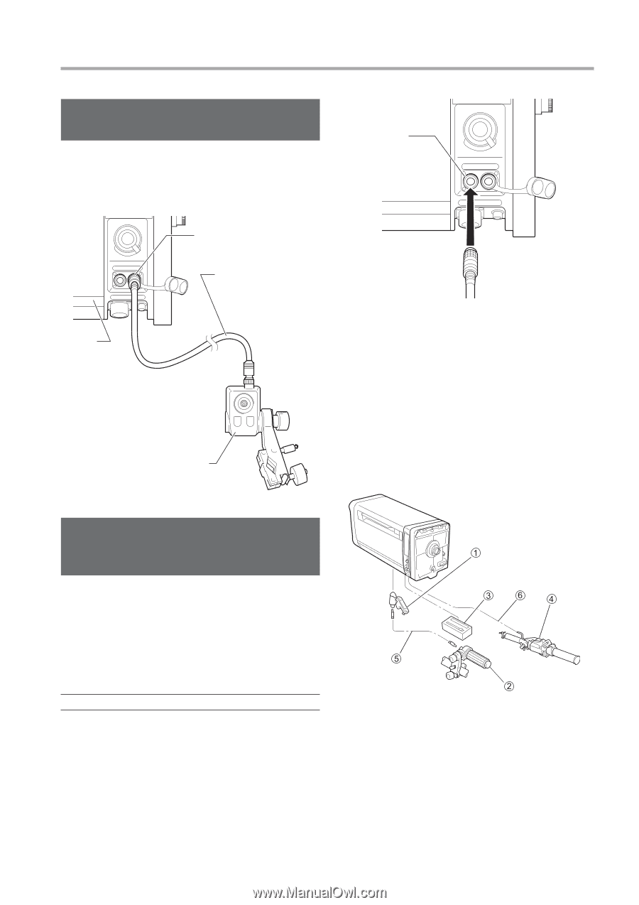
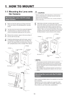
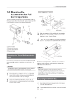
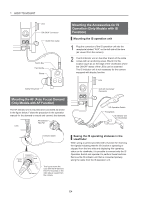
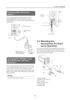
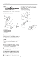
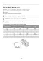
1 HOW TO MOUNT Connecting Wiper Switch Box (Option) When using separately purchased switch box for the wiper equipped lens, connect it to the lens using the dedicated cable. (Connection method varies by switch box specifications.) "VIRTUAL" Connector "SW. BOX" Connector Lens Wiper Switch Box Cable Wiper Switch Box (Shapes and connections vary by specifications.) To Virtual System 1-3 Mounting the Accessories for Semiservo Operation The zoom servo demand and the flexible focus control unit are mounted and connected as shown in the figure below. When mounting the various demands, refer to the operation manual for the respective demand. Connecting the "VIRTUAL" Cable (Only Models with "VIRTUAL" Connector) The lens is equipped with the connector labeled "VIRTUAL" on its left side (as viewed from the camera). This connector can be used for connection with an interface to virtual systems. Zoom, focus and iris signals can be output in three types of communication data; analog signal, encoder pulse train and RS-422. * (NOTE) Connector location may vary by models. ᶃ Flexible module ᶄ Flexible focus control unit ᶅ Servo module ᶆ Zoom servo demand ᶇ Flexible cable ᶈ Demand cable E5
-
 1
1 -
2
-
3
-
4
-
5
-
6
-
7
-
8
-
9
-
10
-
11
-
12
-
13
-
14
-
15
-
16
-
17
-
18
-
19
-
20
-
21
-
22
-
23
-
24
-
25
-
26
-
27
-
28
-
29
-
30
-
31
-
32
-
33
-
34
-
35
-
36
-
37
-
38
-
39
-
40
-
41
-
 42
42 -
 43
43 -
 44
44 -
 45
45 -
 46
46 -
 47
47 -
 48
48 -
 49
49 -
 50
50 -
 51
51 -
 52
52 -
53
-
54
-
55
-
56
-
57
-
58
-
59
-
60
-
61
-
62
-
63
-
64
-
65
-
66
-
67
-
68
-
69
-
70
-
71
-
72
-
73
-
74
-
75
-
76
-
77
-
78
-
79
-
80
-
81
-
82
-
83
-
84
-
85
-
86
-
87
-
88
-
89
-
90
-
91
-
92
-
93
-
94
-
95
-
96
-
97
-
98
-
99
-
100
-
101
-
102
-
103
-
104
-
105
-
106
-
107
-
108
-
109
-
110
-
111
-
112
-
113
-
114
-
115
-
116
-
117
-
118
-
119
-
120
-
121
-
122
-
123
-
124
-
125
-
126
-
127
-
128
-
129
-
130
-
131
-
132
-
133
-
134
-
135
-
136
 |
 |