Cisco 6509E Supervisor Guide - Page 31
Feature, Description, MB p/n MEM-C6K-ATA-1-64M= ATA Flash PC card. An eject button - supervisor slot
 |
View all Cisco 6509E manuals
Add to My Manuals
Save this manual to your list of manuals |
Page 31 highlights
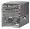
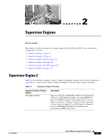
Chapter 2 Supervisor Engines Supervisor Engine 2 Table 2-2 Supervisor Engine 2 Features (continued) Feature Memory SP DRAM SP NVRAM SP onboard flash Front panel features Status LEDs RESET switch CONSOLE port PCMCIA slot options Uplink ports Uplink port queue structure Description • WS-X6K-S2-PFC2 and WS-X6K-S2-MSFC2-128 MB (default); upgradeable to 512 MB. • WS-X6K-S2U-MSFC2-256 MB (default); upgradeable to 512 MB. 512 KB 32 MB See Table 2-4 for a list of the status LEDs and their descriptions. The RESET switch allows you to reset and restart the switch. Note Use a ballpoint pen tip or other small, pointed object to access the RESET button. One 10/100/1000 port that uses an RJ-45 connector. The CONSOLE port allows you to access the switch either locally (with a console terminal) or remotely (with a modem). The CONSOLE port is an EIA/TIA-232 asynchronous, serial connection with hardware flow control. The CONSOLE port has an LED associated with it. One PCMCIA slot is available. The Flash PC card (PCMCIA) slot holds a Flash PC card for additional flash memory. You can use this flash memory to store and run software images or to serve as an I/O device. Supports a 64 MB (p/n MEM-C6K-ATA-1-64M=) ATA Flash PC card. An eject button is located on the right side, next to the slot. Pushing in on the button ejects the Flash PC card from the slot. The PCMCIA slot has an LED associated with it. Supervisor Engine 2 has two 1000BASE-X uplink ports. The two 1000BASE-X uplink ports require GBIC transceivers. The uplink ports have LEDs associated with them. Note In chassis configurations where there are redundant supervisor engines installed, the uplink ports on the supervisor engine that is in standby mode are fully functional. Tx-1p2q2t Rx-1p1q4t OL-7397-03 Catalyst 6500 Series Supervisor Engine Guide 2-3
-
 1
1 -
2
-
3
-
4
-
5
-
6
-
7
-
8
-
9
-
10
-
11
-
12
-
13
-
14
-
15
-
16
-
17
-
18
-
19
-
20
-
21
-
22
-
23
-
24
-
25
-
 26
26 -
 27
27 -
 28
28 -
 29
29 -
 30
30 -
 31
31 -
 32
32 -
 33
33 -
 34
34 -
 35
35 -
 36
36 -
37
-
38
-
39
-
40
-
41
-
42
-
43
-
44
-
45
-
46
-
47
-
48
-
49
-
50
-
51
-
52
-
53
-
54
-
55
-
56
-
57
-
58
-
59
-
60
-
61
-
62
-
63
-
64
-
65
-
66
-
67
-
68
-
69
-
70
-
71
-
72
-
73
-
74
-
75
-
76
-
77
-
78
-
79
-
80
-
81
-
82
-
83
-
84
-
85
-
86
-
87
-
88
-
89
-
90
-
91
-
92
-
93
-
94
-
95
-
96
-
97
-
98
-
99
-
100
-
101
-
102
-
103
-
104
-
105
-
106
-
107
-
108
-
109
-
110
 |
 |
