Cisco 6509E Supervisor Guide - Page 80
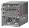
Removing the Supervisor Engine Horizontal Slot Chassis Shown - air flow
 |
View all Cisco 6509E manuals
Add to My Manuals
Save this manual to your list of manuals |
Page 80 highlights
Removing a Supervisor Engine Chapter 3 Installing Supervisor Engines Figure 3-6 Removing the Supervisor Engine (Horizontal Slot Chassis Shown) 1 2 WS-X6624-FXS 3 STATUS 1 4 7 10 13 16 19 22 2 5 8 11 14 17 20 23 3 6 9 12 15 18 21 24 24 PORT FXS ANALOG STATION WS-X6624-FXS 4 STATUS 1 4 7 10 13 16 19 22 2 5 8 11 14 17 20 23 3 6 9 12 15 18 21 24 24 PORT FXS ANALOG STATION 5 WS-X6348-RJ-45V 12 6 24-1 24-1 12 14 24 26 1 2 3 4 5 6 7 8 9 10 11 12 48 PORT 10/100 BASE-T 13 14 15 16 17 18 19 20 21 22 23 24 ETHERNET SWITCHING MODULE 25 26 27 28 36 38 48 34 35 36 37 38 39 40 41 42 43 44 45 46 47 48 o o INPUT OK FAN OUTPUT OK FAIL INPUT OK FAN OUTPUT OK FAIL 130907 Step 6 Step 7 Place the removed module on an antistatic mat or in an antistatic bag, or immediately reinstall it in another slot. If the slot is to remain empty, install a module filler plate to keep dust out of the chassis and to maintain proper airflow through the chassis. If a Supervisor Engine 2T or a WS-X6908-10G module is installed, the slots adjacent to either the supervisor engine or the module must have switching-module filler plates installed (Cisco part numbers WS-X6K-SLOT-CVR-E or SLOTBLANK-09). Do not install blank slot covers (WS-X6K-SLOT-CVR). Warning Blank faceplates and cover panels serve three important functions: they prevent exposure to hazardous voltages and currents inside the chassis; they contain electromagnetic interference (EMI) that might disrupt other equipment; and they direct the flow of cooling air through the chassis. Do not operate the system unless all cards, faceplates, front covers, and rear covers are in place. Statement 1029 Warning Invisible laser radiation may be emitted from disconnected fibers or connectors. Do not stare into beams or view directly with optical instruments. Statement 1051 3-12 Catalyst 6500 Series Supervisor Engine Guide OL-7397-03
-
 1
1 -
2
-
3
-
4
-
5
-
6
-
7
-
8
-
9
-
10
-
11
-
12
-
13
-
14
-
15
-
16
-
17
-
18
-
19
-
20
-
21
-
22
-
23
-
24
-
25
-
26
-
27
-
28
-
29
-
30
-
31
-
32
-
33
-
34
-
35
-
36
-
37
-
38
-
39
-
40
-
41
-
42
-
43
-
44
-
45
-
46
-
47
-
48
-
49
-
50
-
51
-
52
-
53
-
54
-
55
-
56
-
57
-
58
-
59
-
60
-
61
-
62
-
63
-
64
-
65
-
66
-
67
-
68
-
69
-
70
-
71
-
72
-
73
-
74
-
 75
75 -
 76
76 -
 77
77 -
 78
78 -
 79
79 -
 80
80 -
 81
81 -
 82
82 -
 83
83 -
 84
84 -
 85
85 -
86
-
87
-
88
-
89
-
90
-
91
-
92
-
93
-
94
-
95
-
96
-
97
-
98
-
99
-
100
-
101
-
102
-
103
-
104
-
105
-
106
-
107
-
108
-
109
-
110
 |
 |
