Cisco 891W Hardware Installation Guide - Page 106
Console and Auxiliary Port Connector Pinouts
 |
View all Cisco 891W manuals
Add to My Manuals
Save this manual to your list of manuals |
Page 106 highlights
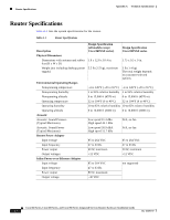
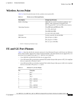
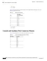
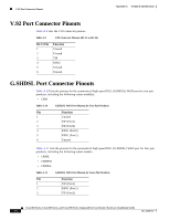
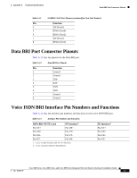
Console and Auxiliary Port Connector Pinouts Appendix A Technical Specifications 1. RX = Receive 2. TX = Transmit Table A-4 describes the RJ-45 connector pinouts for the Gigabit Ethernet (GE) ports of the Cisco 860VAE and 860VAE-K9 ISRs. Table A-4 Ethernet GE Port Pinouts Pin 1 2 3 4 5 6 7 8 1. TX = Transmit 2. RX = Receive GE Signal (LAN and WAN) Tx A+1 Tx ARx B+2 Tx C+ Tx CRx BRx D+ Rx D- Console and Auxiliary Port Connector Pinouts Table A-5 lists the pinouts for the console and auxiliary port connectors. Table A-5 Console and Auxiliary Port Connector Pinouts RJ-45 Pin 1 2 3 4 5 6 7 8 Function RTS DTR TXD GND GND RXD DSR CTS Cisco 860 Series, Cisco 880 Series, and Cisco 890 Series Integrated Services Routers Hardware Installation Guide A-4 OL-16193-07
-
 1
1 -
2
-
3
-
4
-
5
-
6
-
7
-
8
-
9
-
10
-
11
-
12
-
13
-
14
-
15
-
16
-
17
-
18
-
19
-
20
-
21
-
22
-
23
-
24
-
25
-
26
-
27
-
28
-
29
-
30
-
31
-
32
-
33
-
34
-
35
-
36
-
37
-
38
-
39
-
40
-
41
-
42
-
43
-
44
-
45
-
46
-
47
-
48
-
49
-
50
-
51
-
52
-
53
-
54
-
55
-
56
-
57
-
58
-
59
-
60
-
61
-
62
-
63
-
64
-
65
-
66
-
67
-
68
-
69
-
70
-
71
-
72
-
73
-
74
-
75
-
76
-
77
-
78
-
79
-
80
-
81
-
82
-
83
-
84
-
85
-
86
-
87
-
88
-
89
-
90
-
91
-
92
-
93
-
94
-
95
-
96
-
97
-
98
-
99
-
100
-
 101
101 -
 102
102 -
 103
103 -
 104
104 -
 105
105 -
 106
106 -
 107
107 -
 108
108 -
 109
109 -
 110
110 -
 111
111 -
112
 |
 |
