Cisco 891W Hardware Installation Guide - Page 84
Securing the Power Cord, Power lock clip
 |
View all Cisco 891W manuals
Add to My Manuals
Save this manual to your list of manuals |
Page 84 highlights
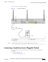
Connecting the AC Adapter Chapter 3 Connecting the Router Step 2 To secure the power cord to the router, attach the power lock clip to the power cord, slide the clip to the end of the DC plug, and secure the retaining clip into the router chassis. See Figure 3-26. Figure 3-26 Securing the Power Cord 3 2 4 1 270659 1 Power lock clip 2 Power cord 3 DC plug 4 Lock holes on either side of the power connector Cisco 860 Series, Cisco 880 Series, and Cisco 890 Series Integrated Services Routers Hardware Installation Guide 3-28 OL-16193-07
-
 1
1 -
2
-
3
-
4
-
5
-
6
-
7
-
8
-
9
-
10
-
11
-
12
-
13
-
14
-
15
-
16
-
17
-
18
-
19
-
20
-
21
-
22
-
23
-
24
-
25
-
26
-
27
-
28
-
29
-
30
-
31
-
32
-
33
-
34
-
35
-
36
-
37
-
38
-
39
-
40
-
41
-
42
-
43
-
44
-
45
-
46
-
47
-
48
-
49
-
50
-
51
-
52
-
53
-
54
-
55
-
56
-
57
-
58
-
59
-
60
-
61
-
62
-
63
-
64
-
65
-
66
-
67
-
68
-
69
-
70
-
71
-
72
-
73
-
74
-
75
-
76
-
77
-
78
-
 79
79 -
 80
80 -
 81
81 -
 82
82 -
 83
83 -
 84
84 -
 85
85 -
 86
86 -
 87
87 -
 88
88 -
 89
89 -
90
-
91
-
92
-
93
-
94
-
95
-
96
-
97
-
98
-
99
-
100
-
101
-
102
-
103
-
104
-
105
-
106
-
107
-
108
-
109
-
110
-
111
-
112
 |
 |

3-28
Cisco 860 Series, Cisco 880 Series, and Cisco 890 Series Integrated Services Routers Hardware Installation Guide
OL-16193-07
Chapter 3
Connecting the Router
Connecting the AC Adapter
Step 2
To secure the power cord to the router, attach the power lock clip to the power cord, slide the clip to the
end of the DC plug, and secure the retaining clip into the router chassis. See
Figure 3-26
.
Figure 3-26
Securing the Power Cord
1
Power lock clip
3
DC plug
2
Power cord
4
Lock holes on either side of the power
connector
270659
4
2
1
3